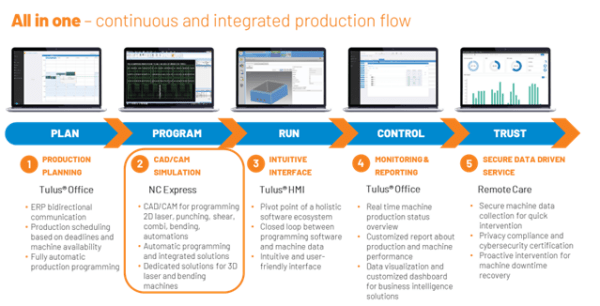
Following Prima Power software strategy ‘All in one’ which aims to create a continuous and integrated production flow for all Prima Power machines, I’m pleased to announce the release of NC Express.
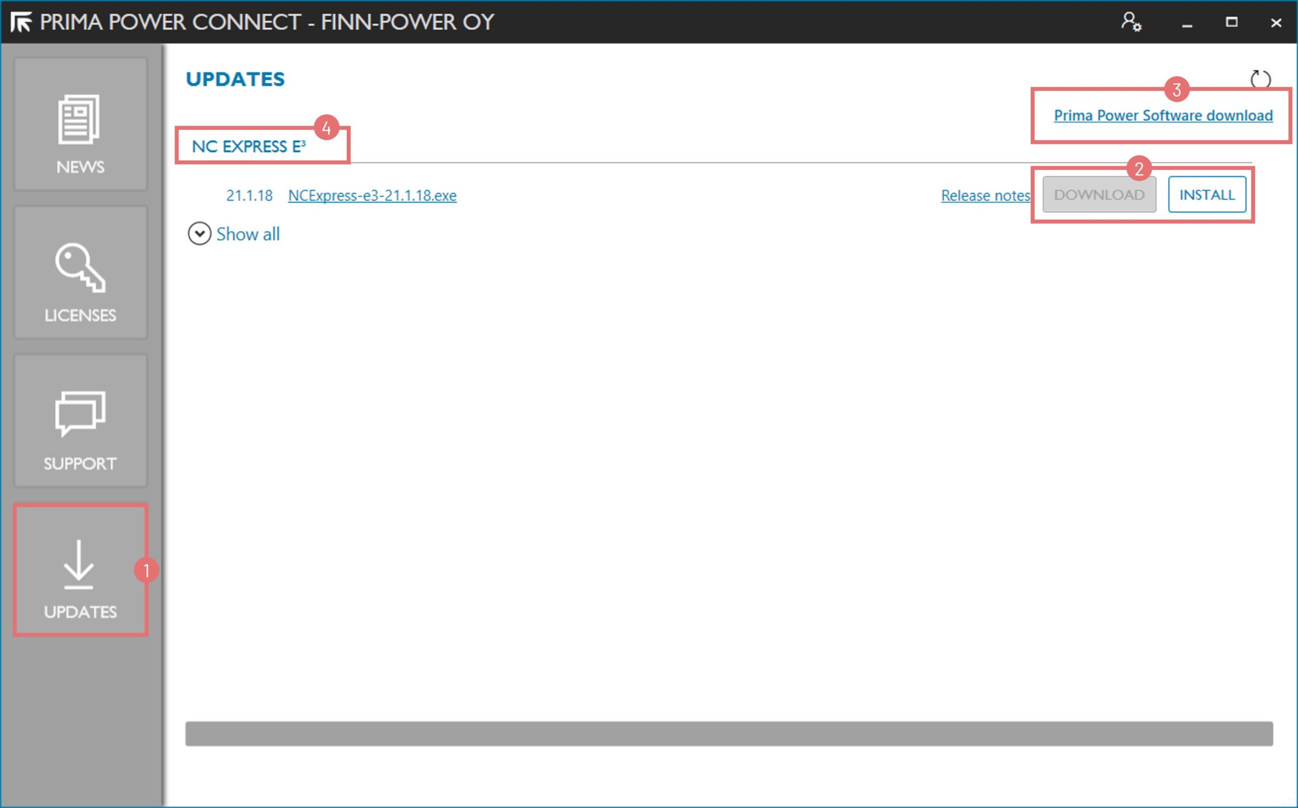
NC Express 25.1 technical release notes document about new features.
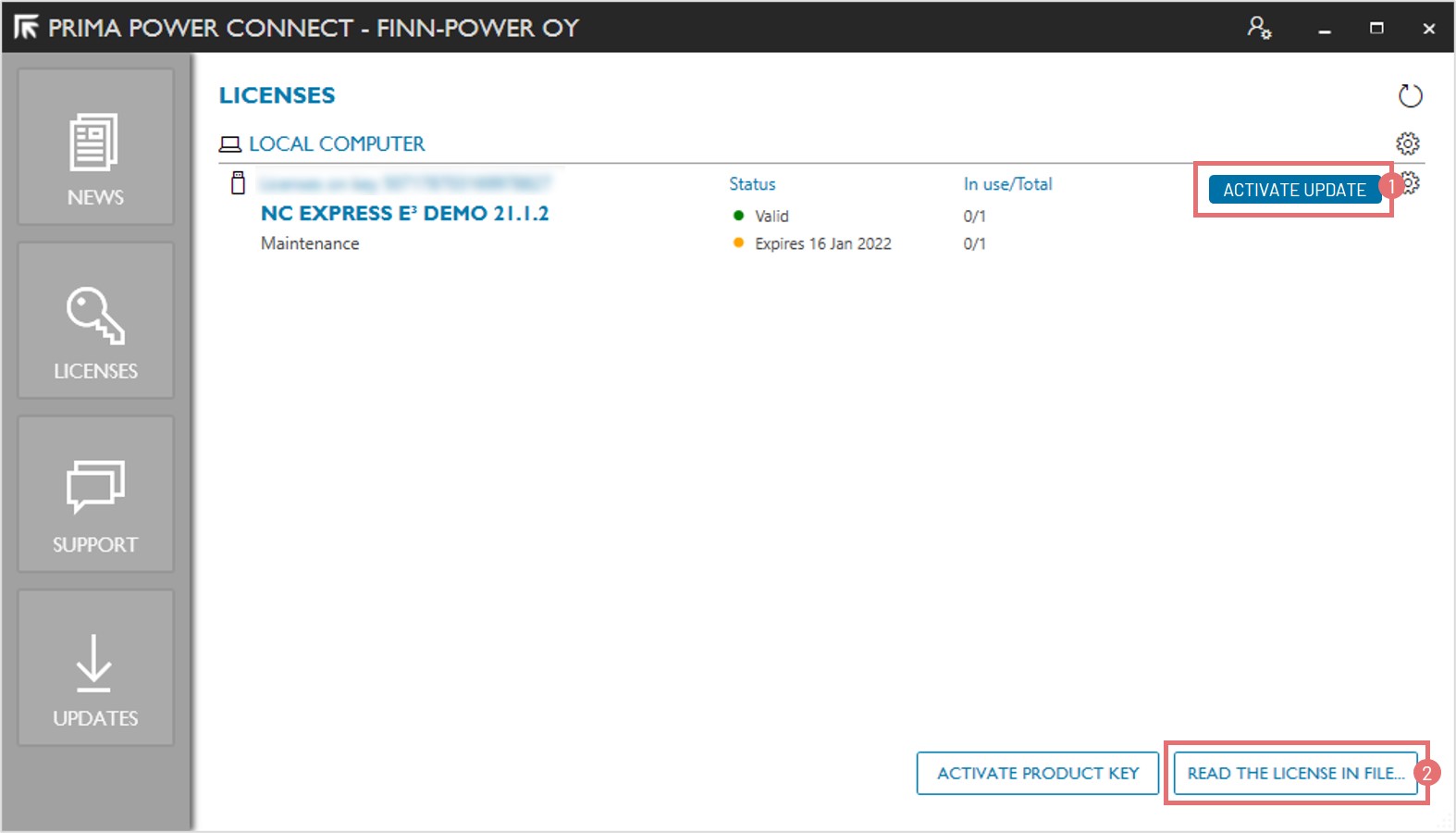
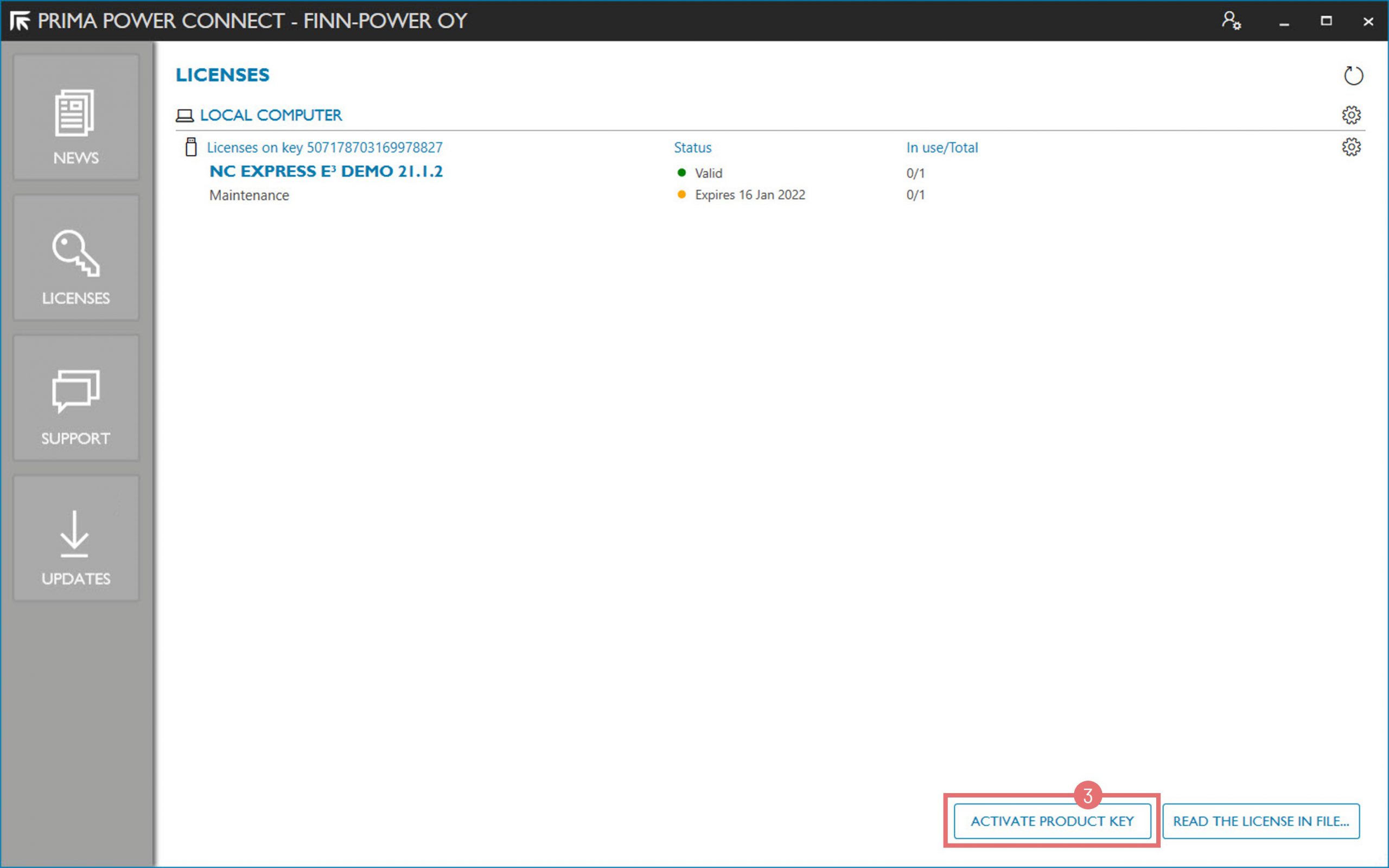
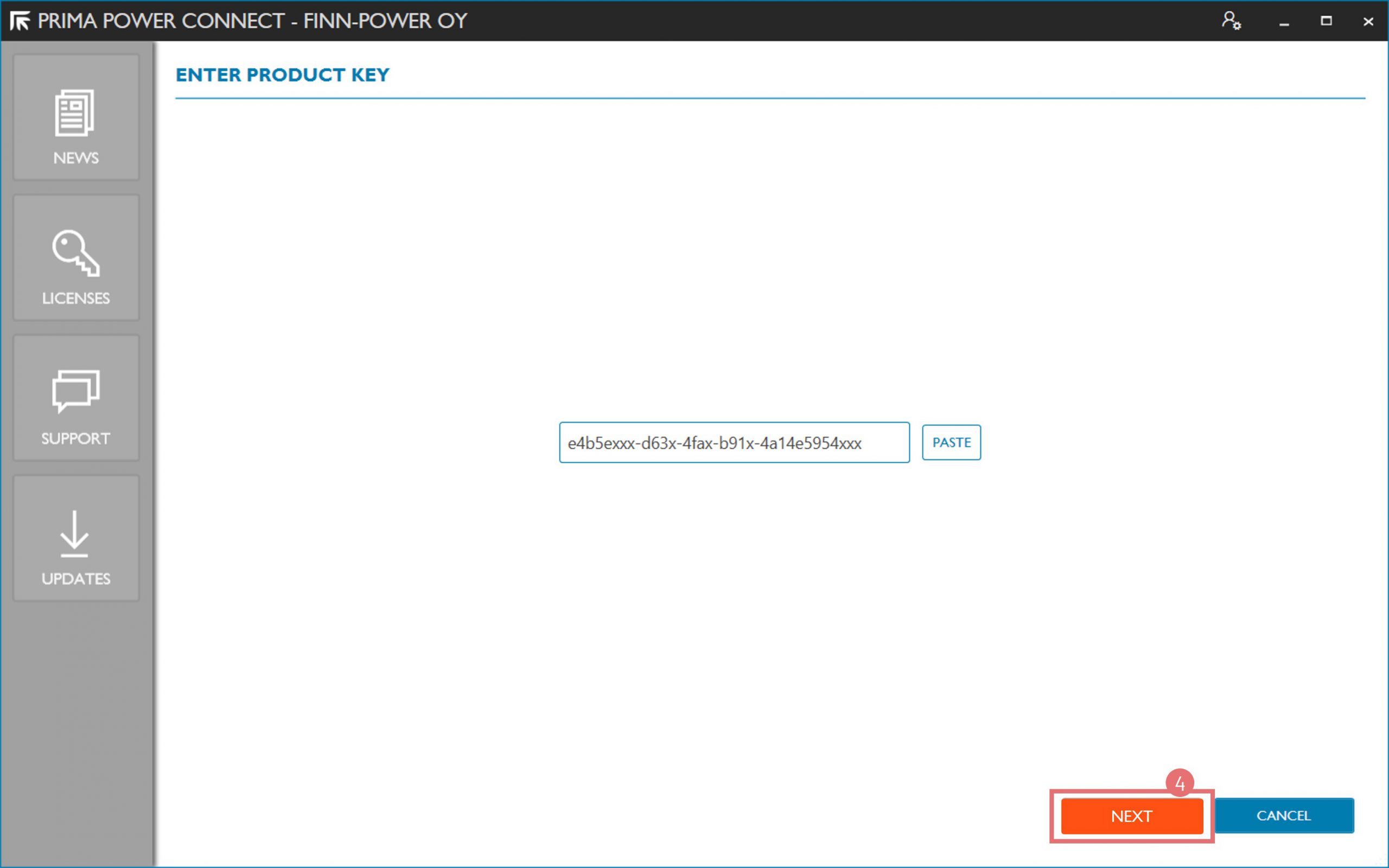
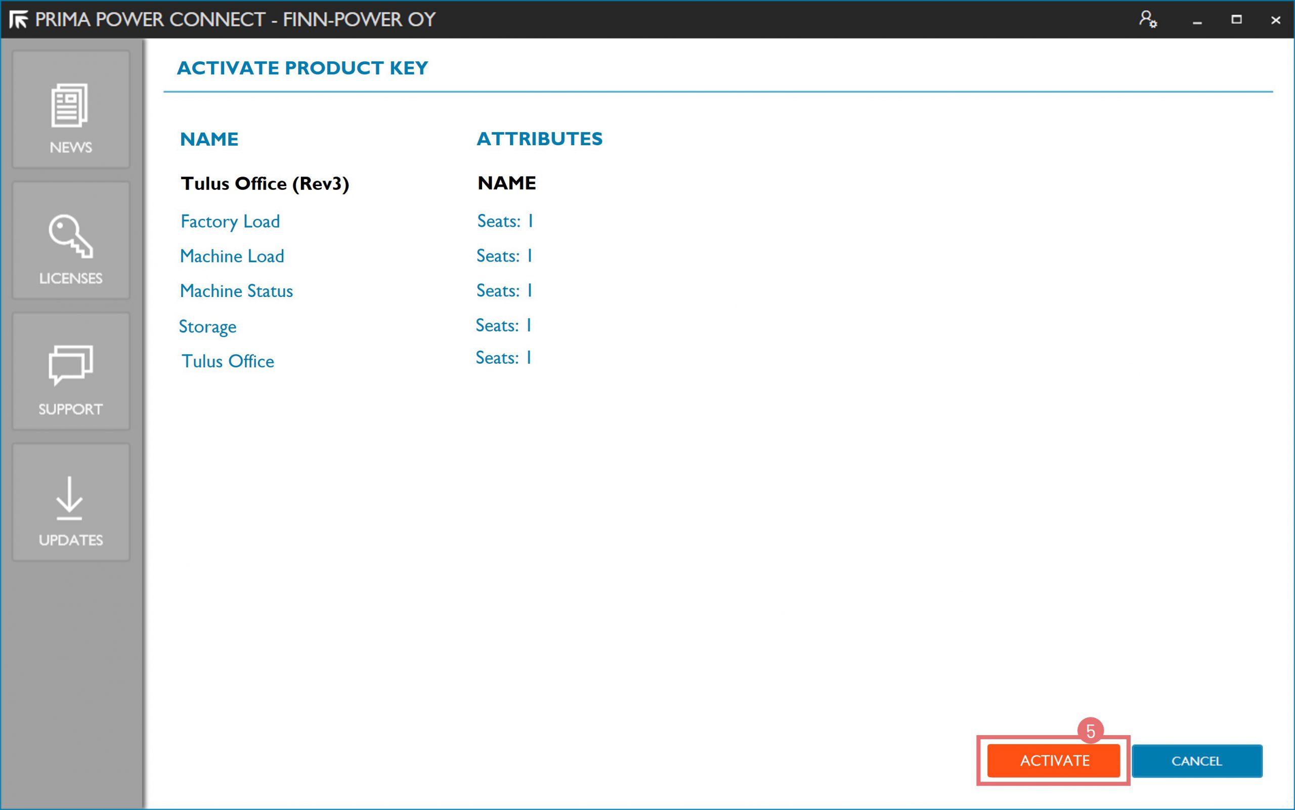
You are entitled to this update when your license maintenance is valid.
Key Highlights of NC Express 25.1:
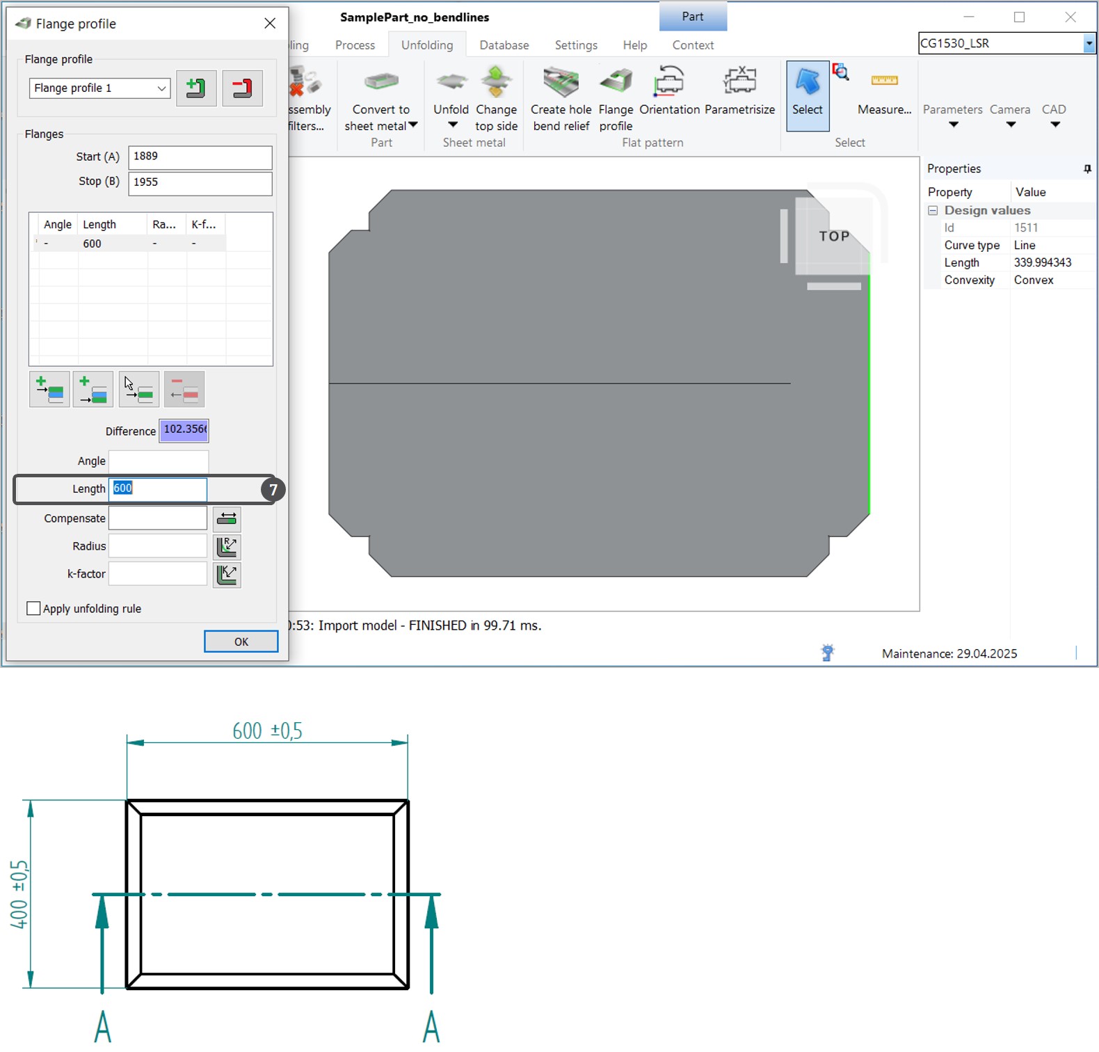
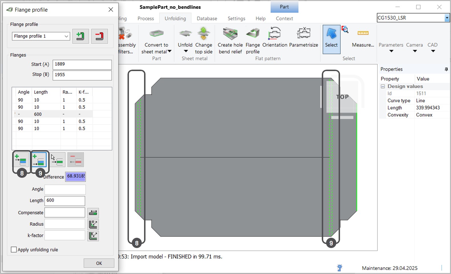
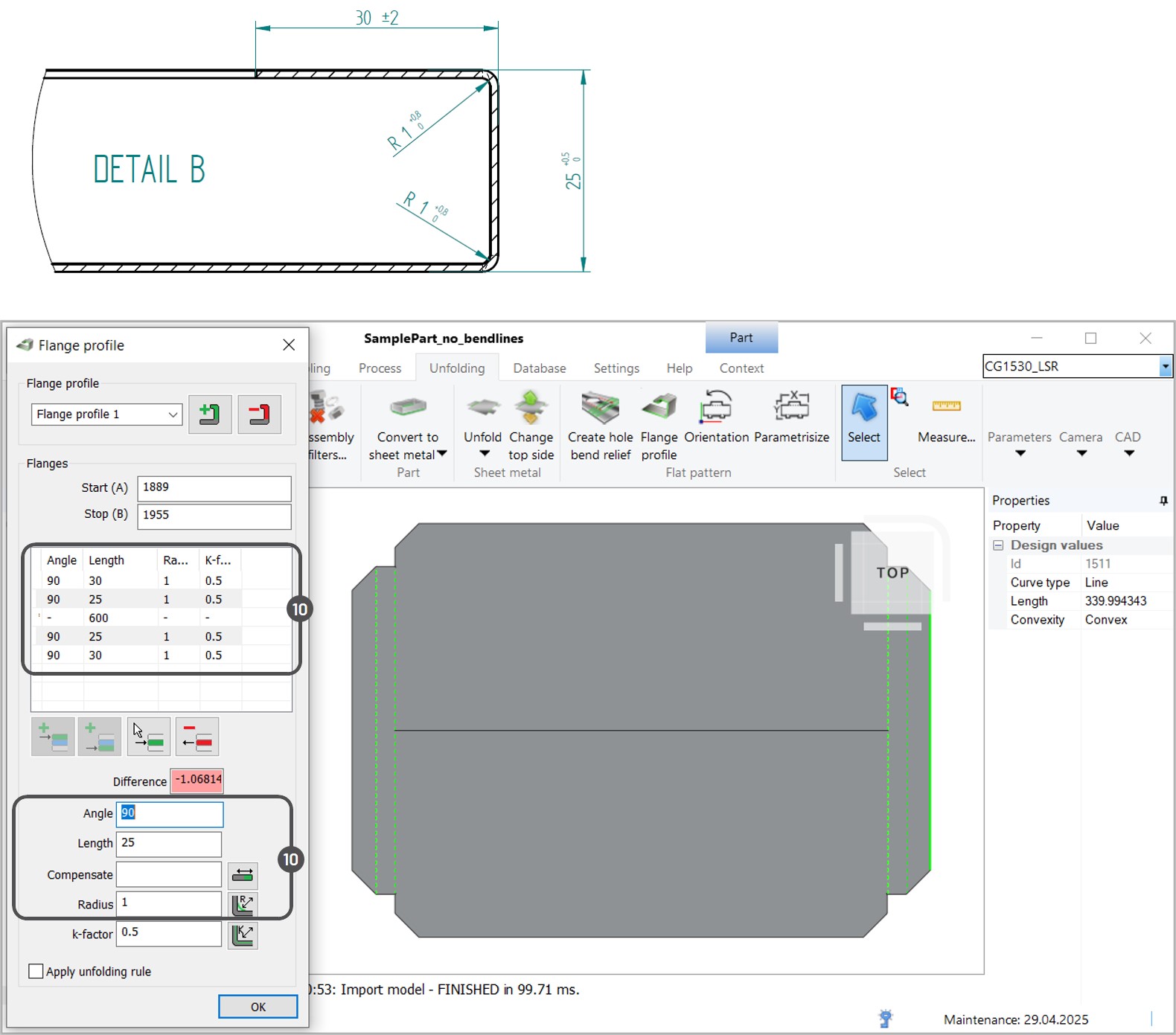
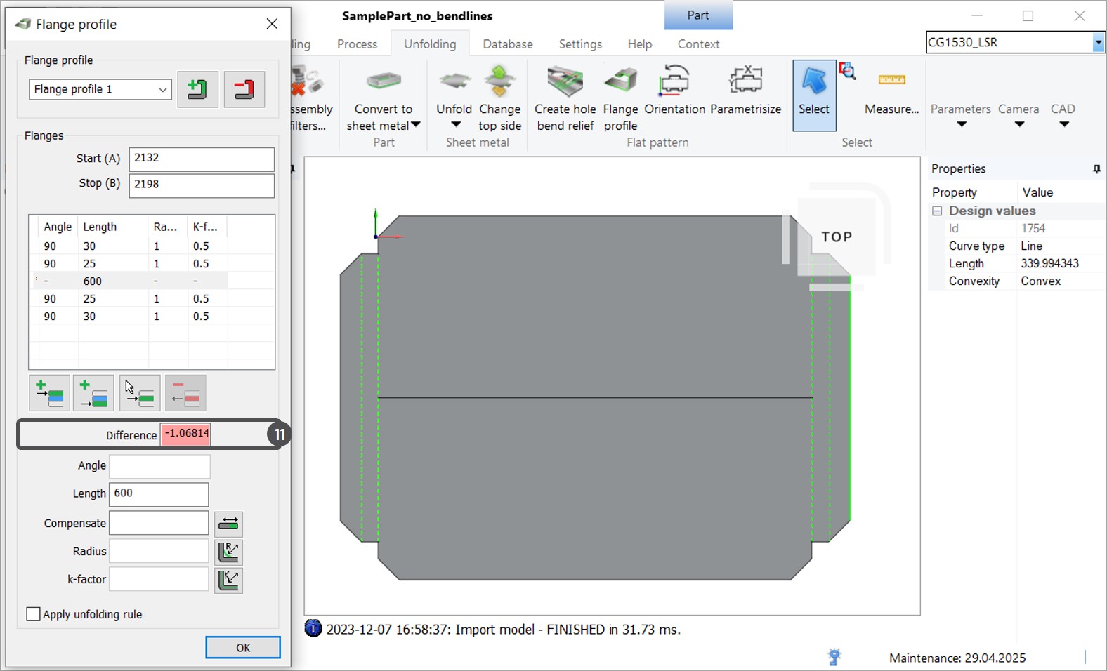
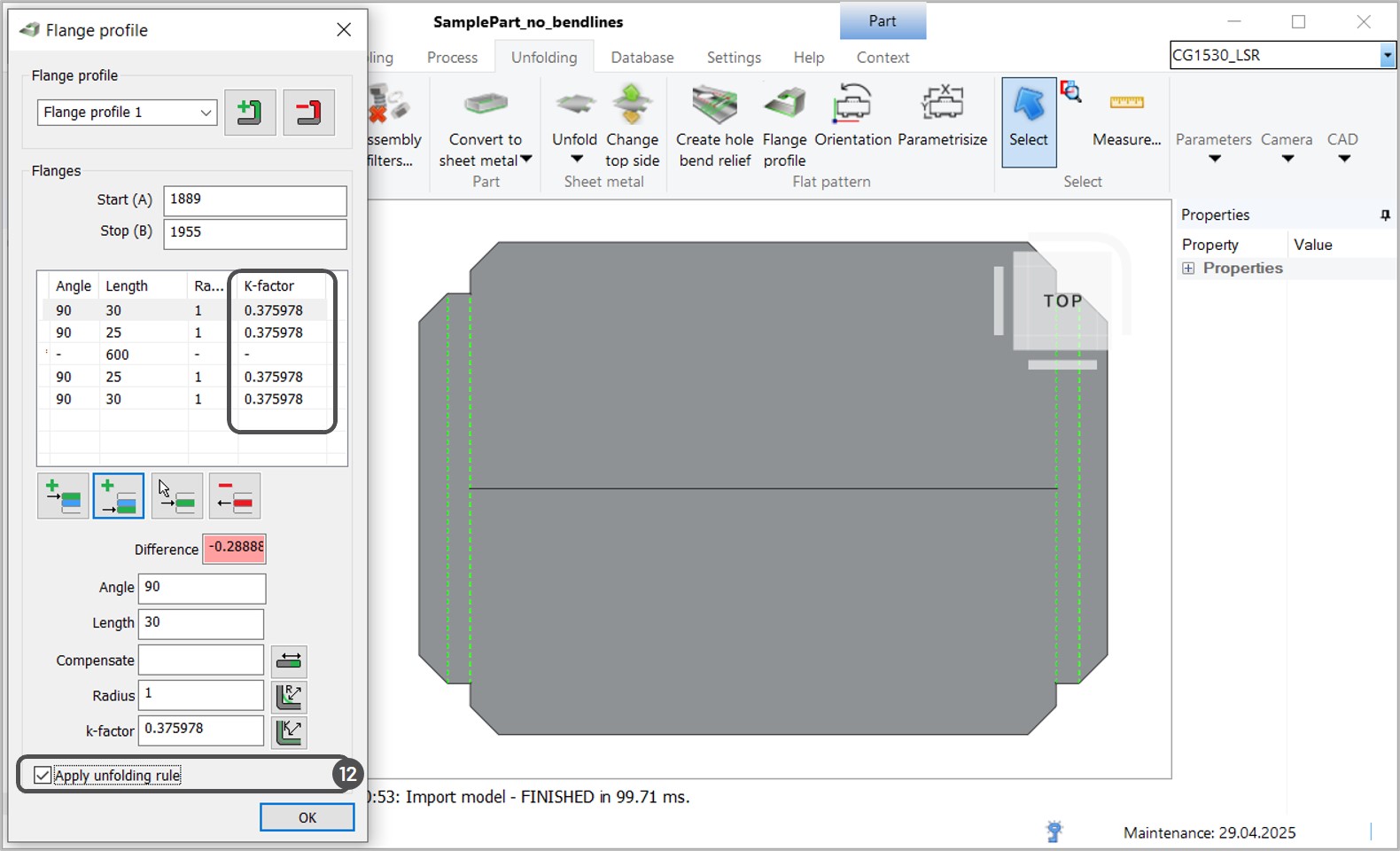
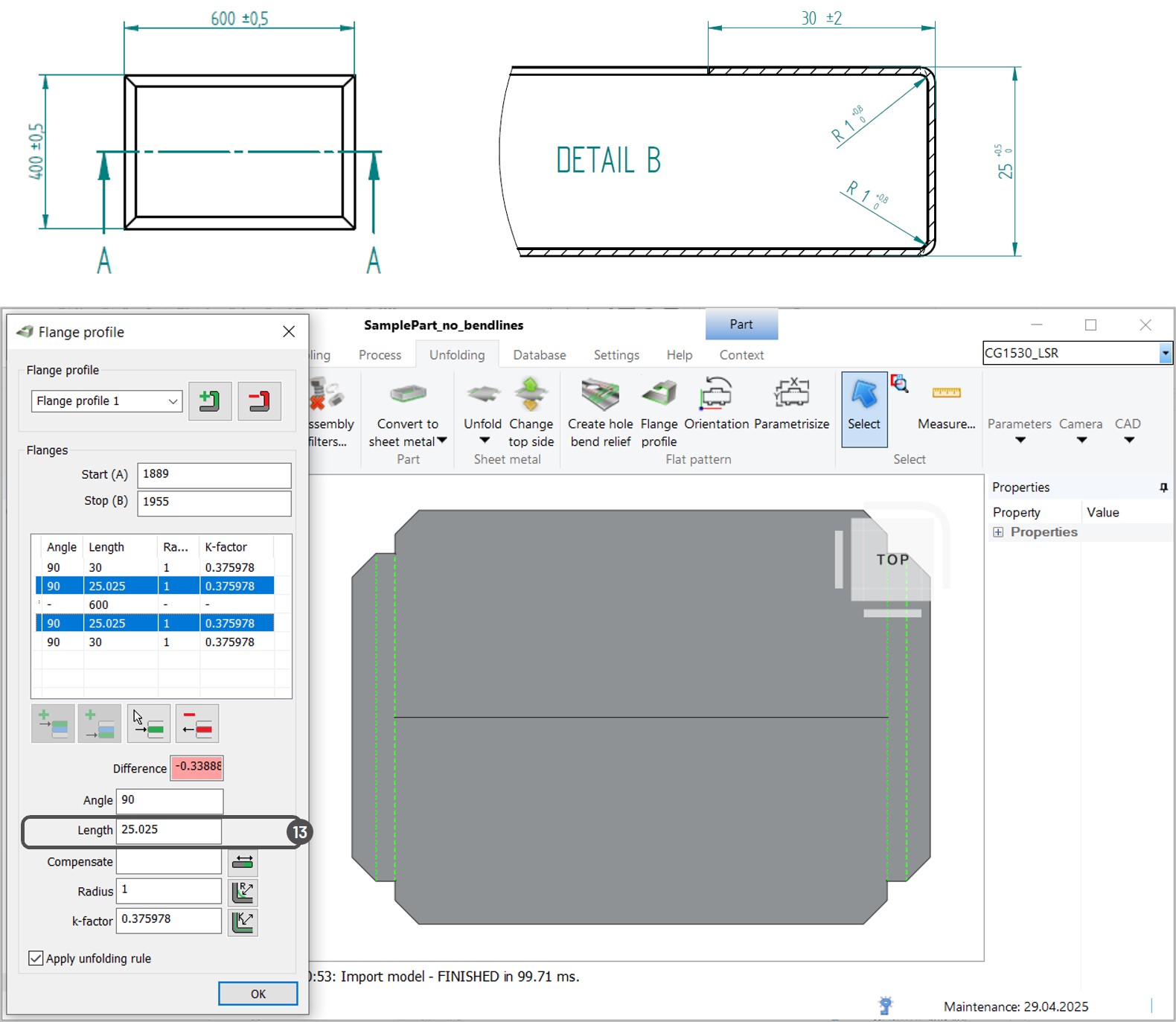
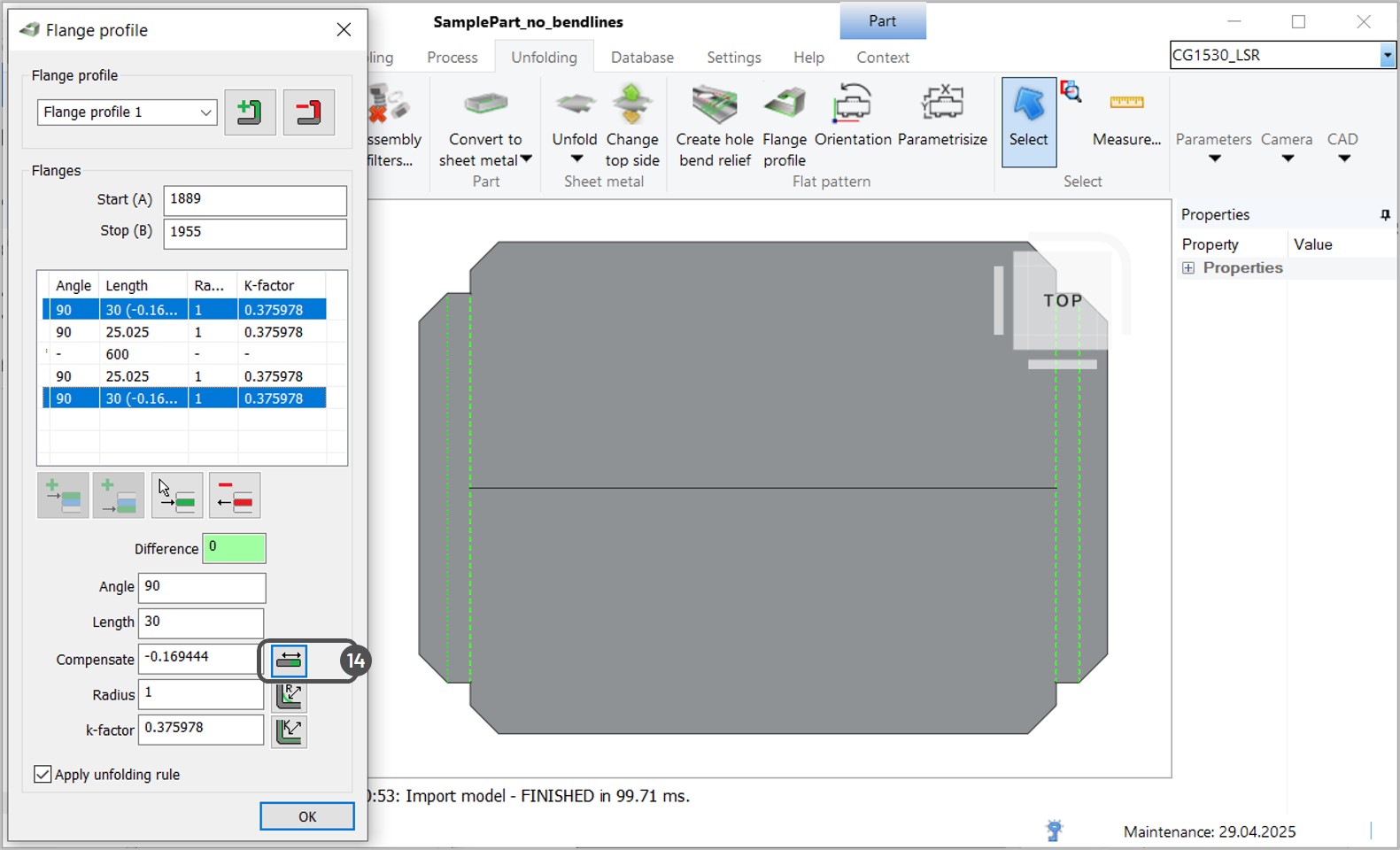
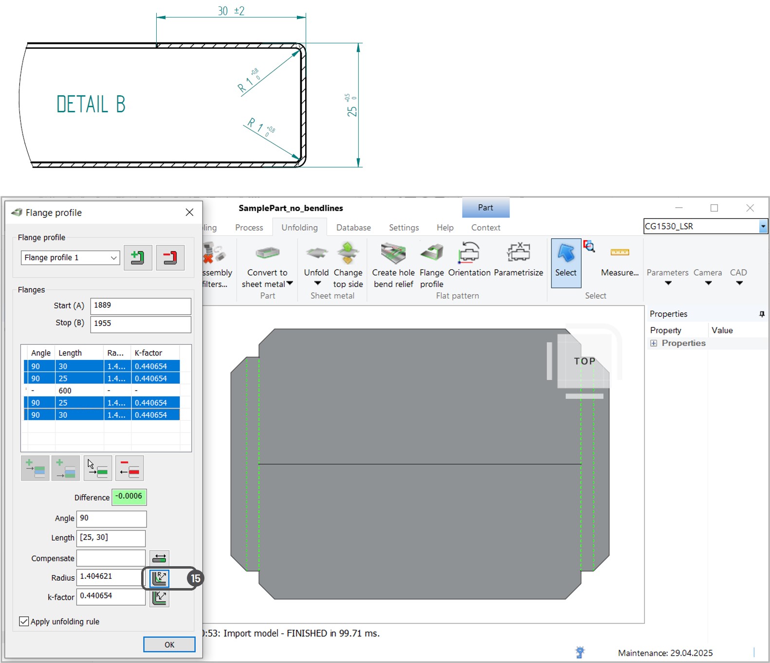
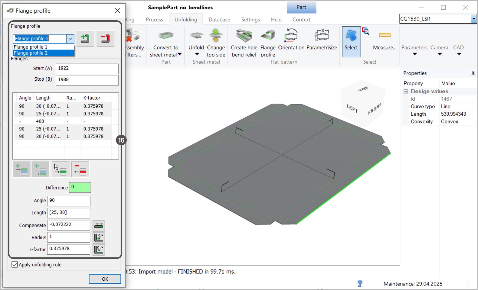
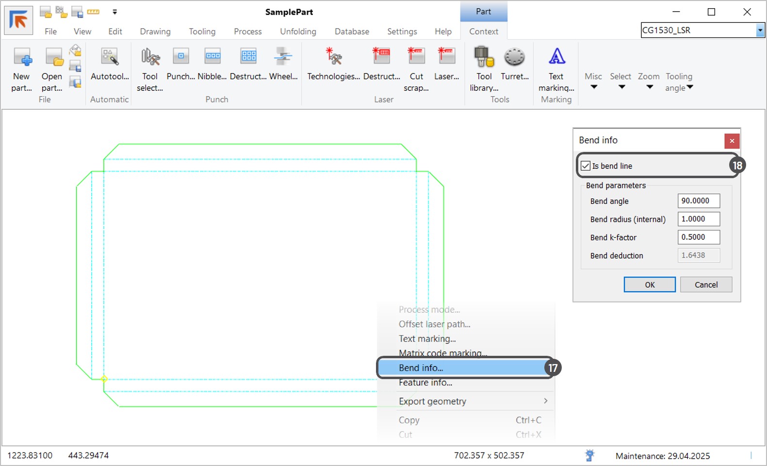
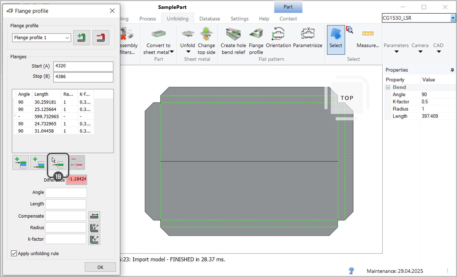
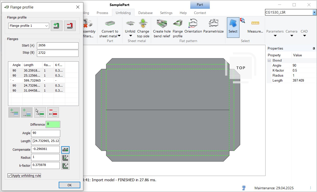
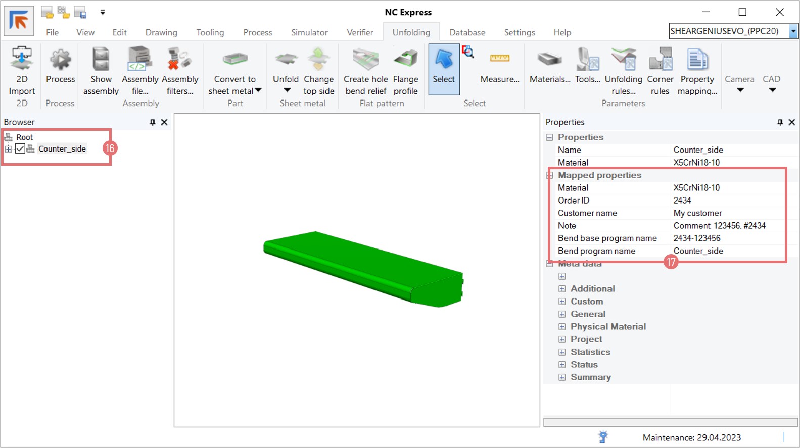
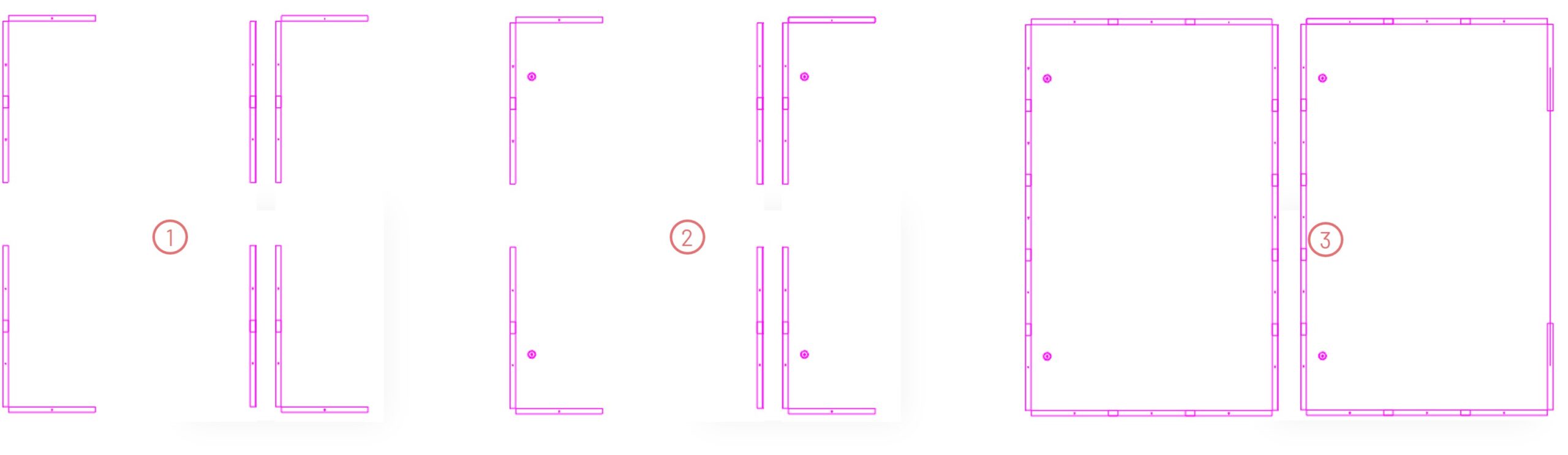
Unfolding & Visualization
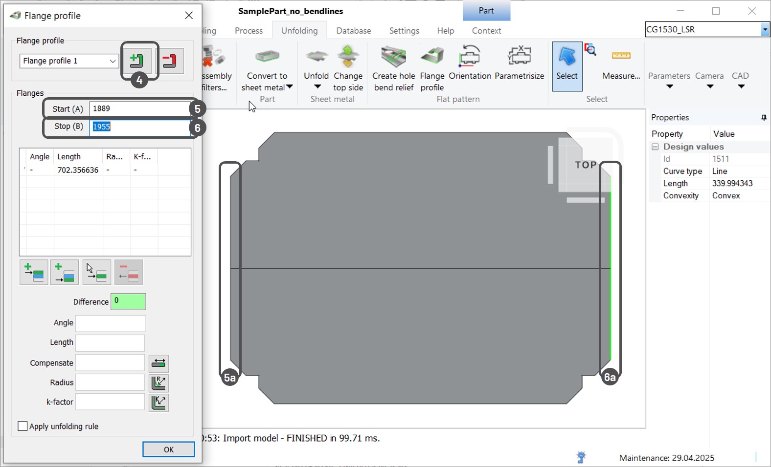
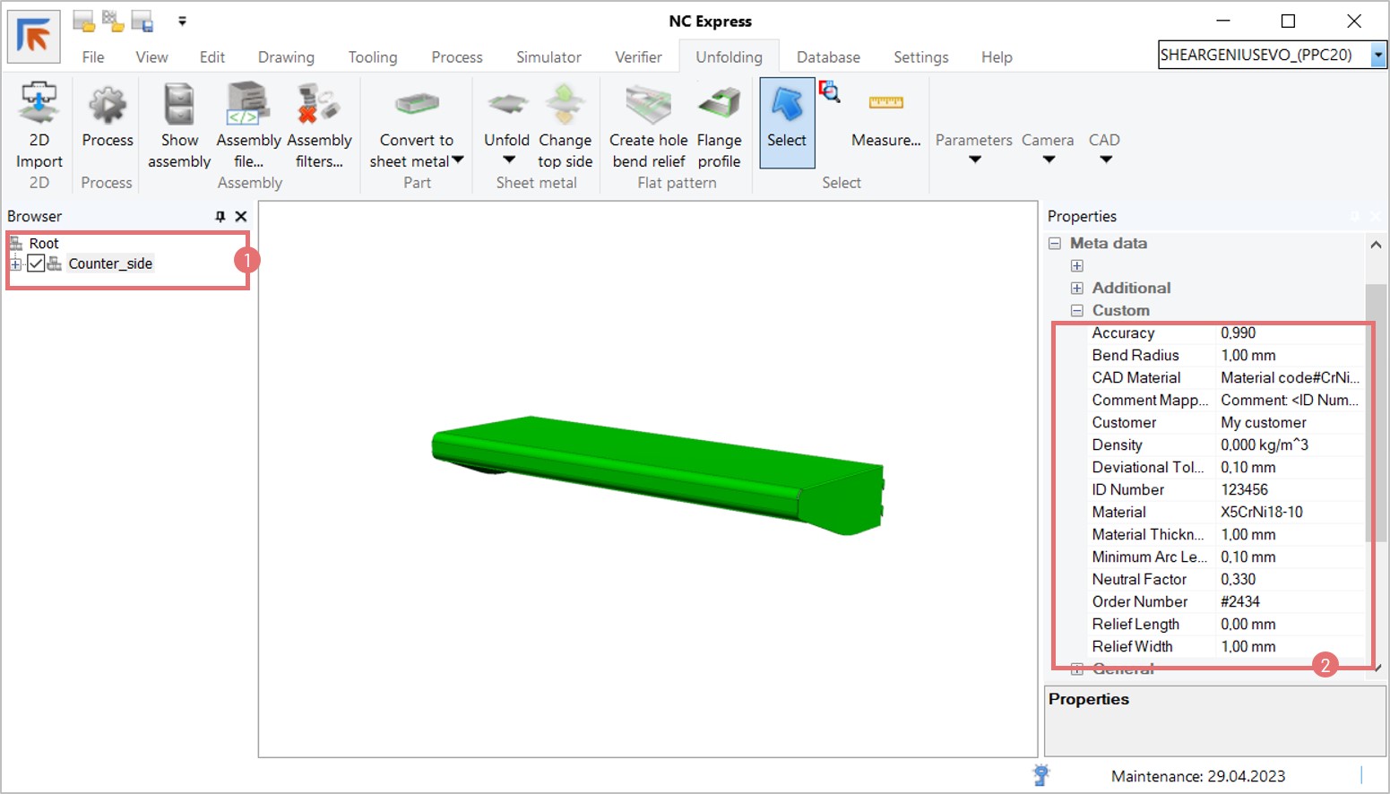
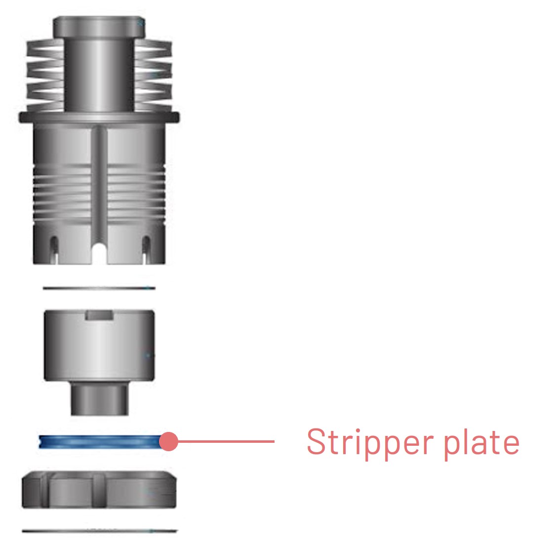
- Top Side Coloring Change: Top side of parts now shown in green or blue depending on plastic protection, reversing previous color conventions.
- Improved 3D Format Handling: Broader support for importing and unfolding complex part geometries.
- Updated 3D Format Support: Expanded compatibility with major CAD formats like Inventor, SolidWorks, Catia, NX, Creo, and more—up to their 2025 versions.
Machine-Specific Features
BEND Machines
- USS Picking Phase: New programmable phase for gripper positioning and stack handling.
- ACP Enhancements: Allows initial part rotation and better nesting for UCP parts.
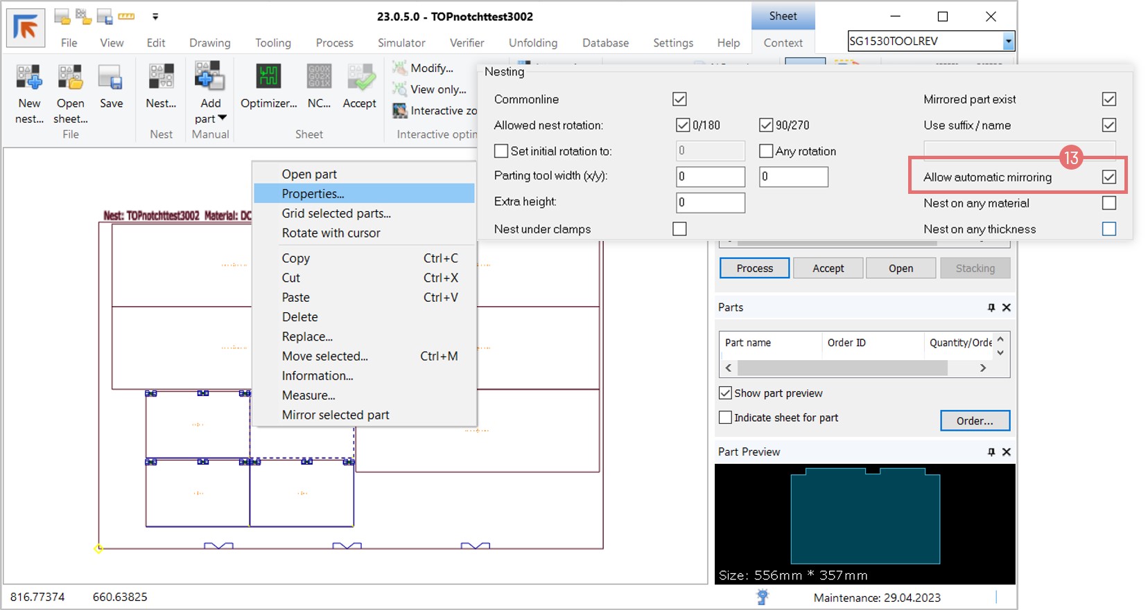
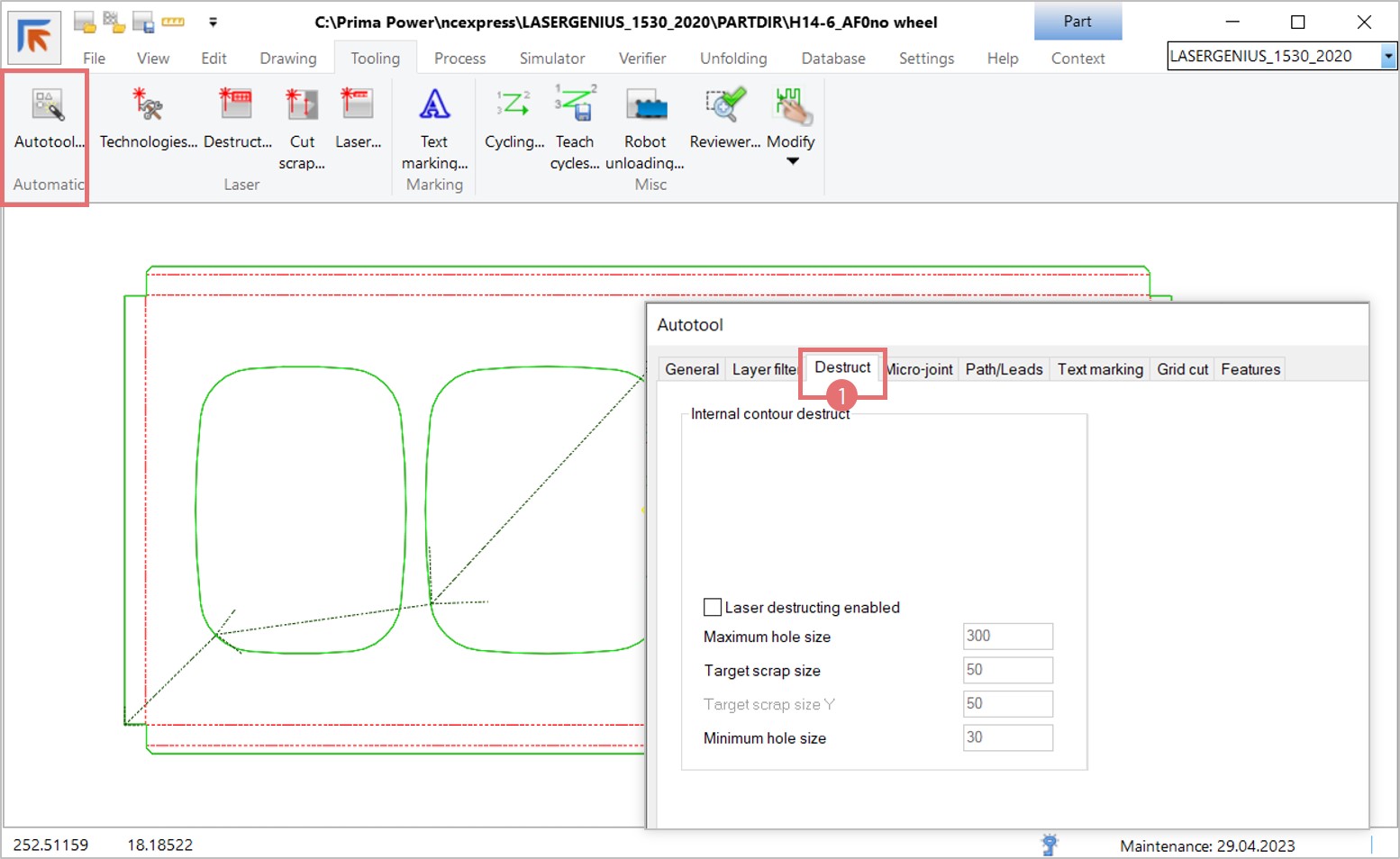
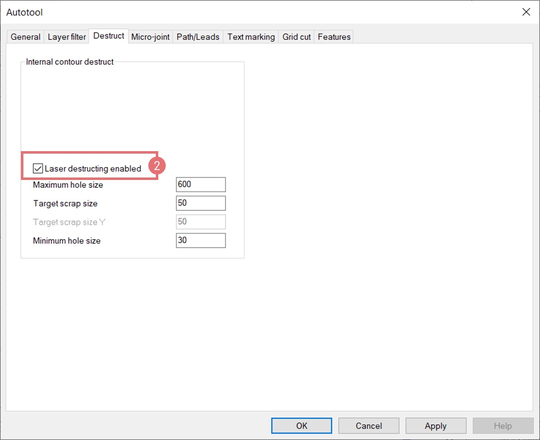
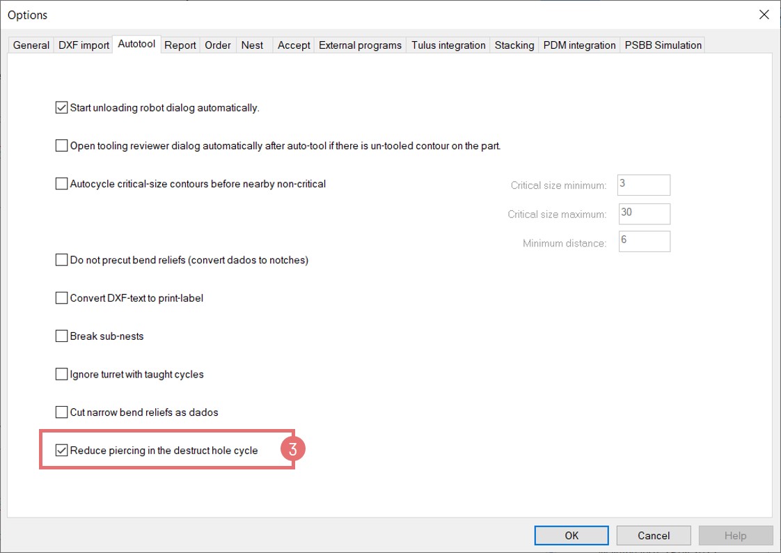
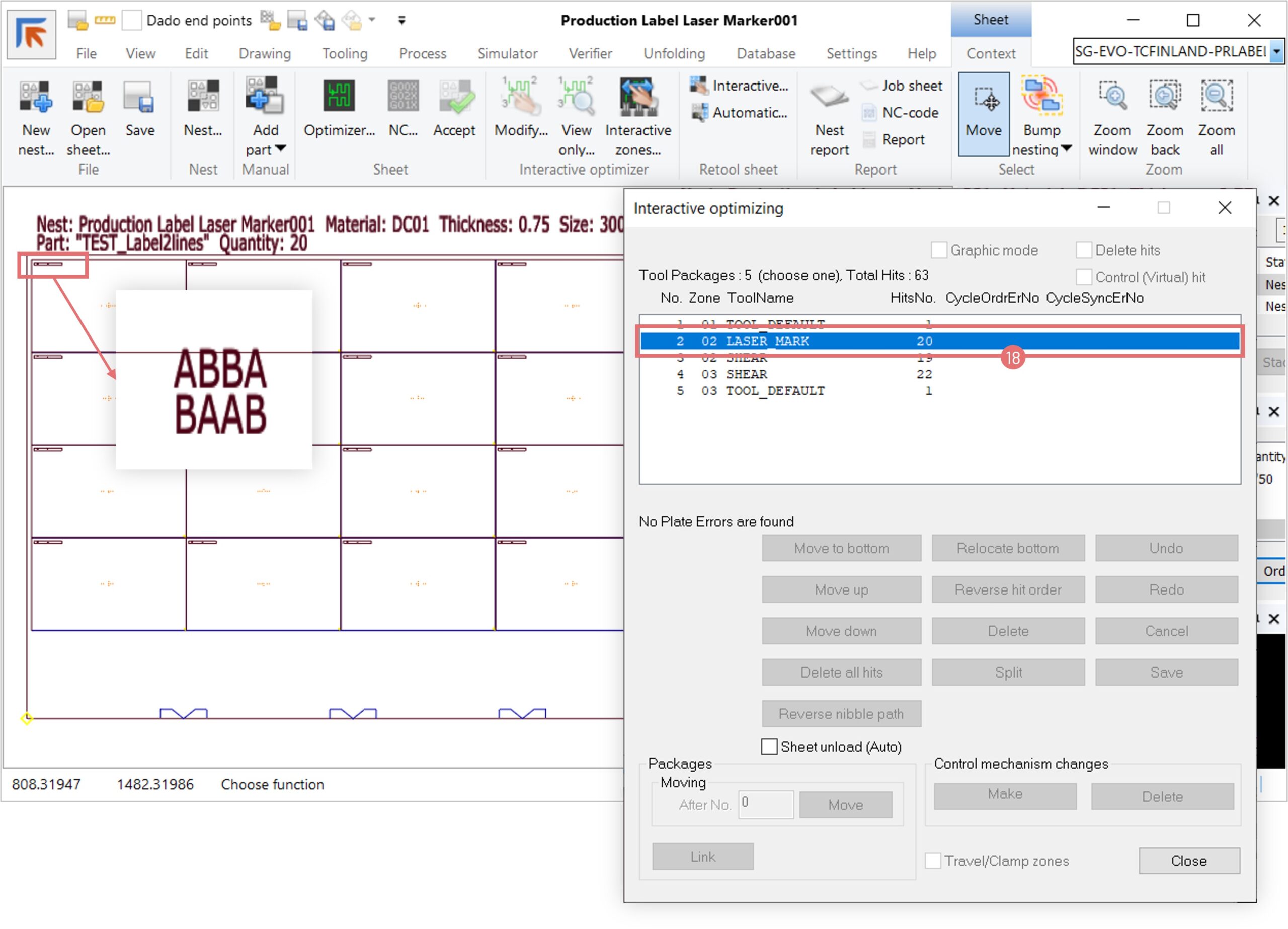
LASER Machines
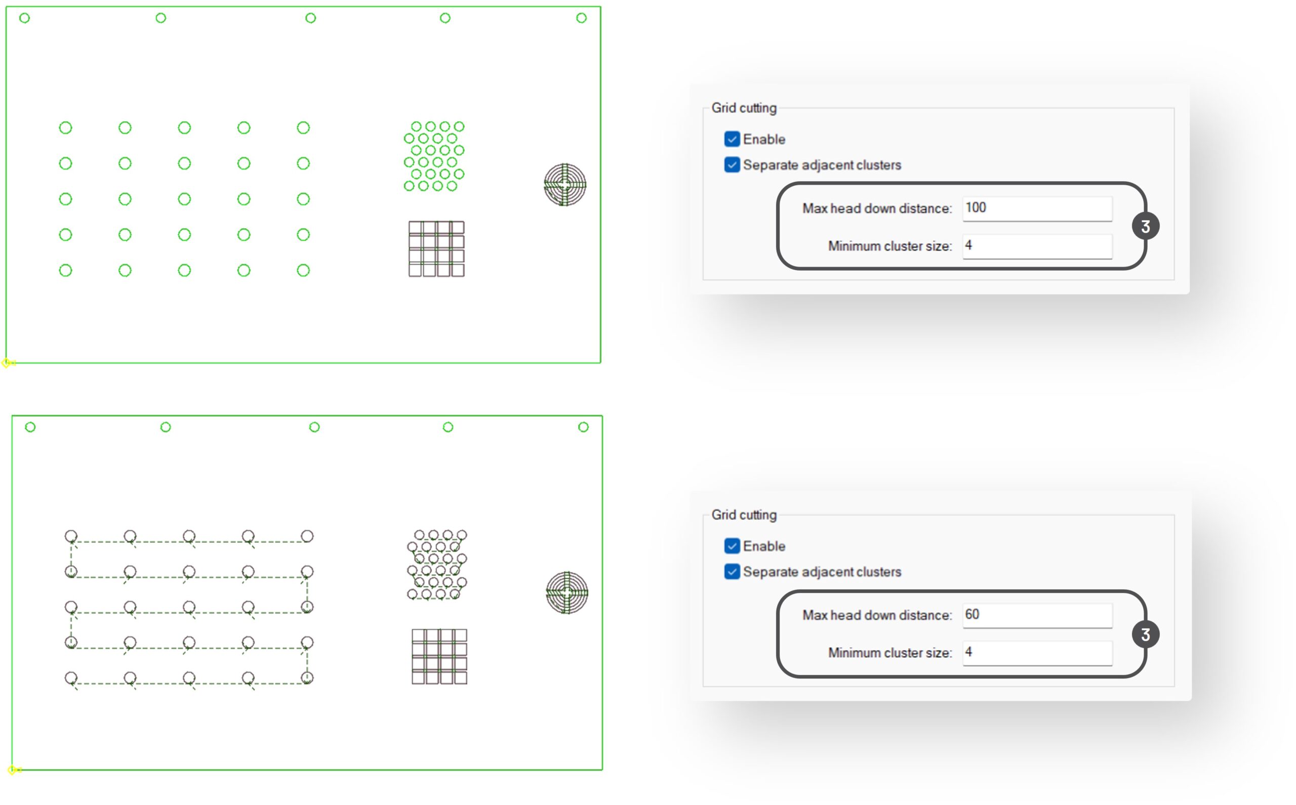
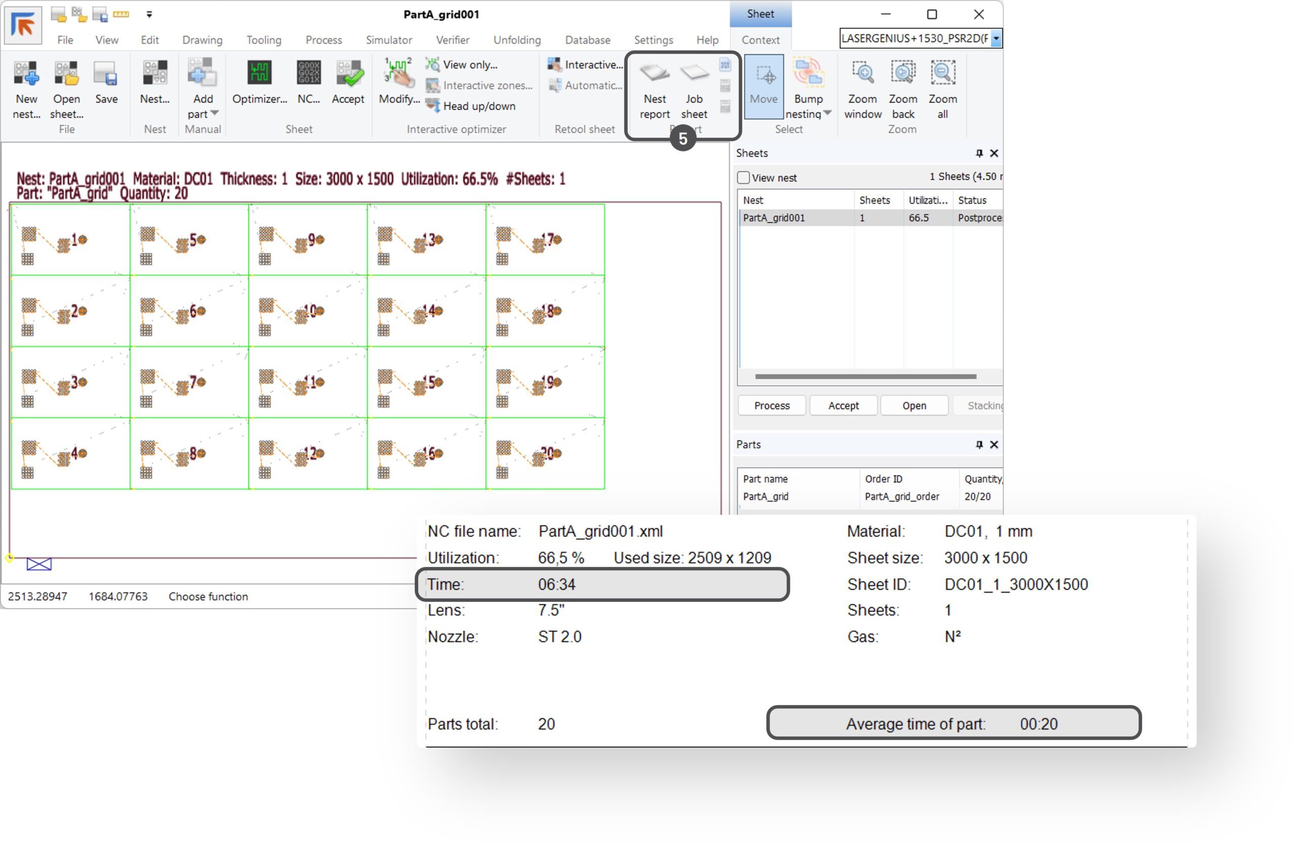
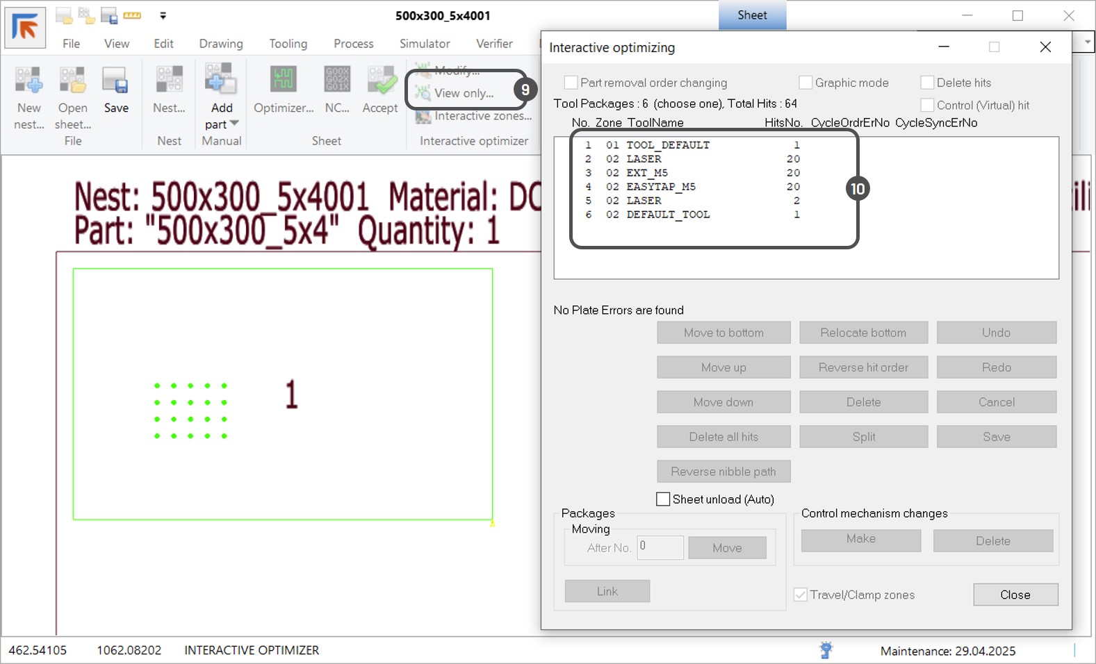
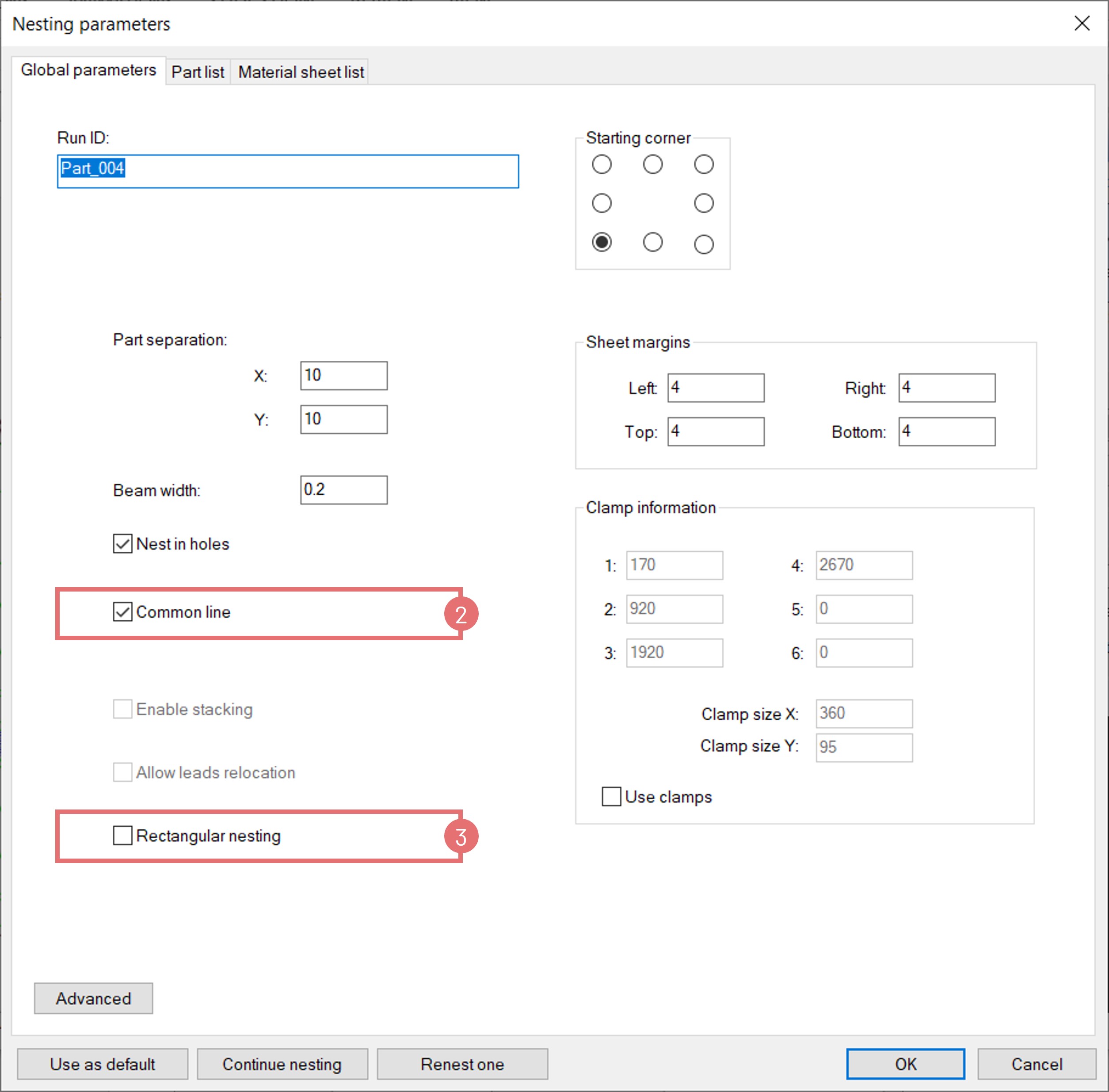
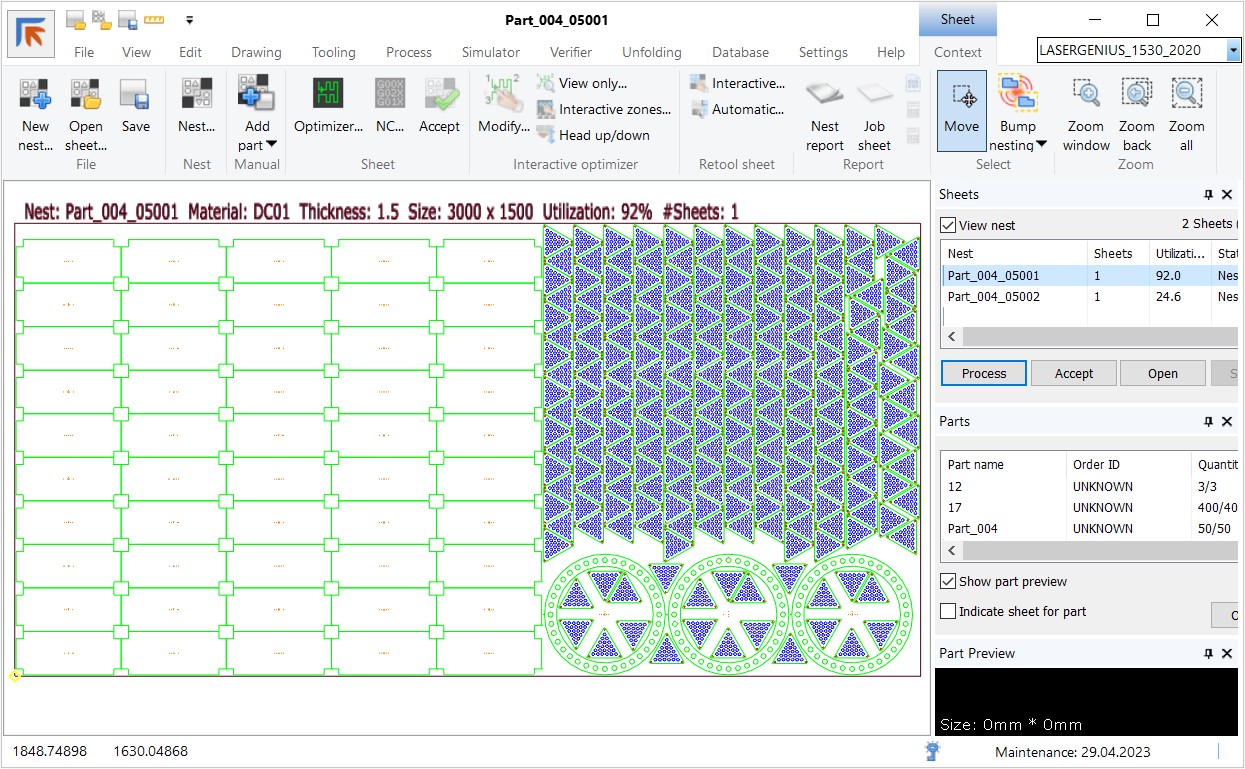
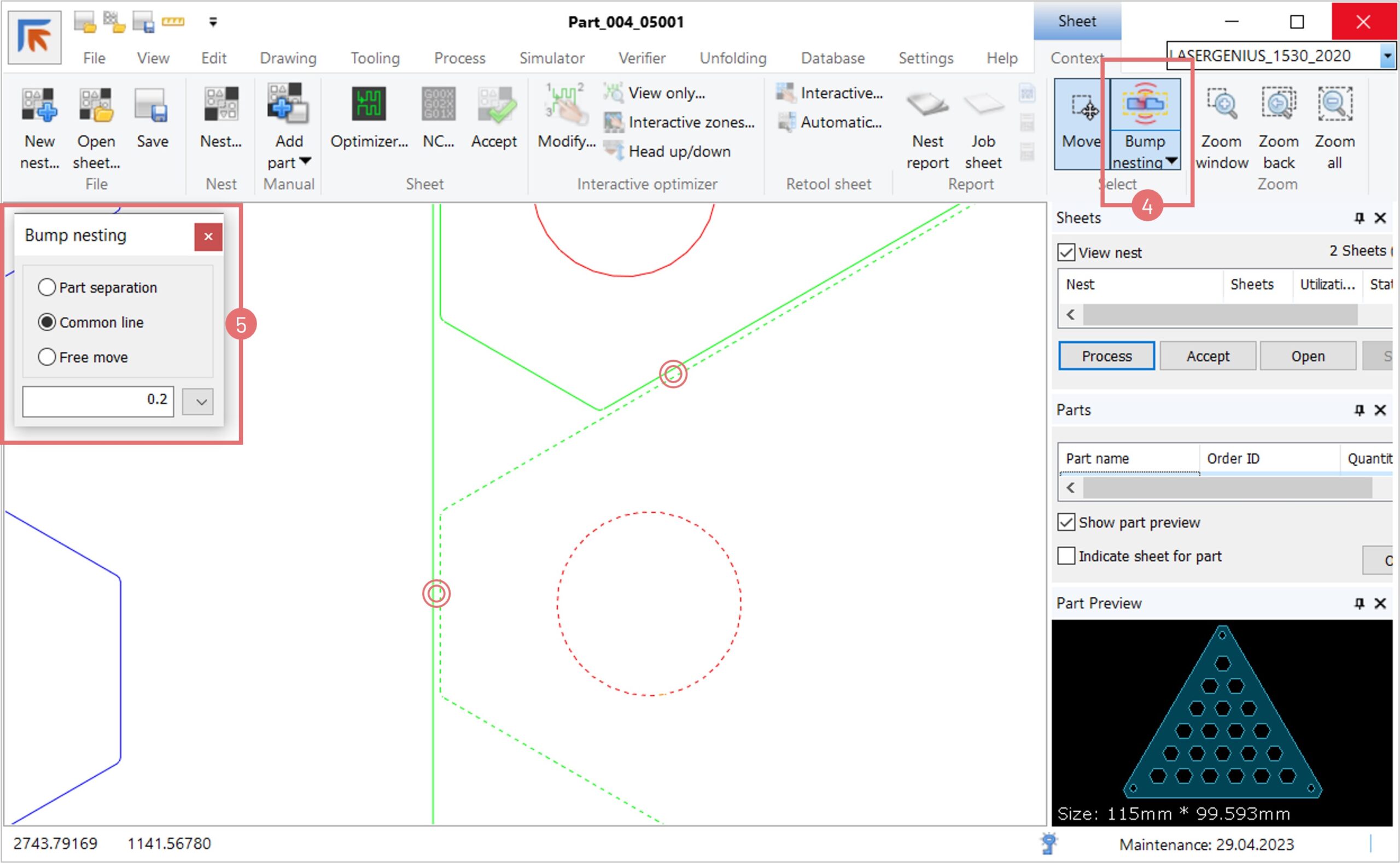
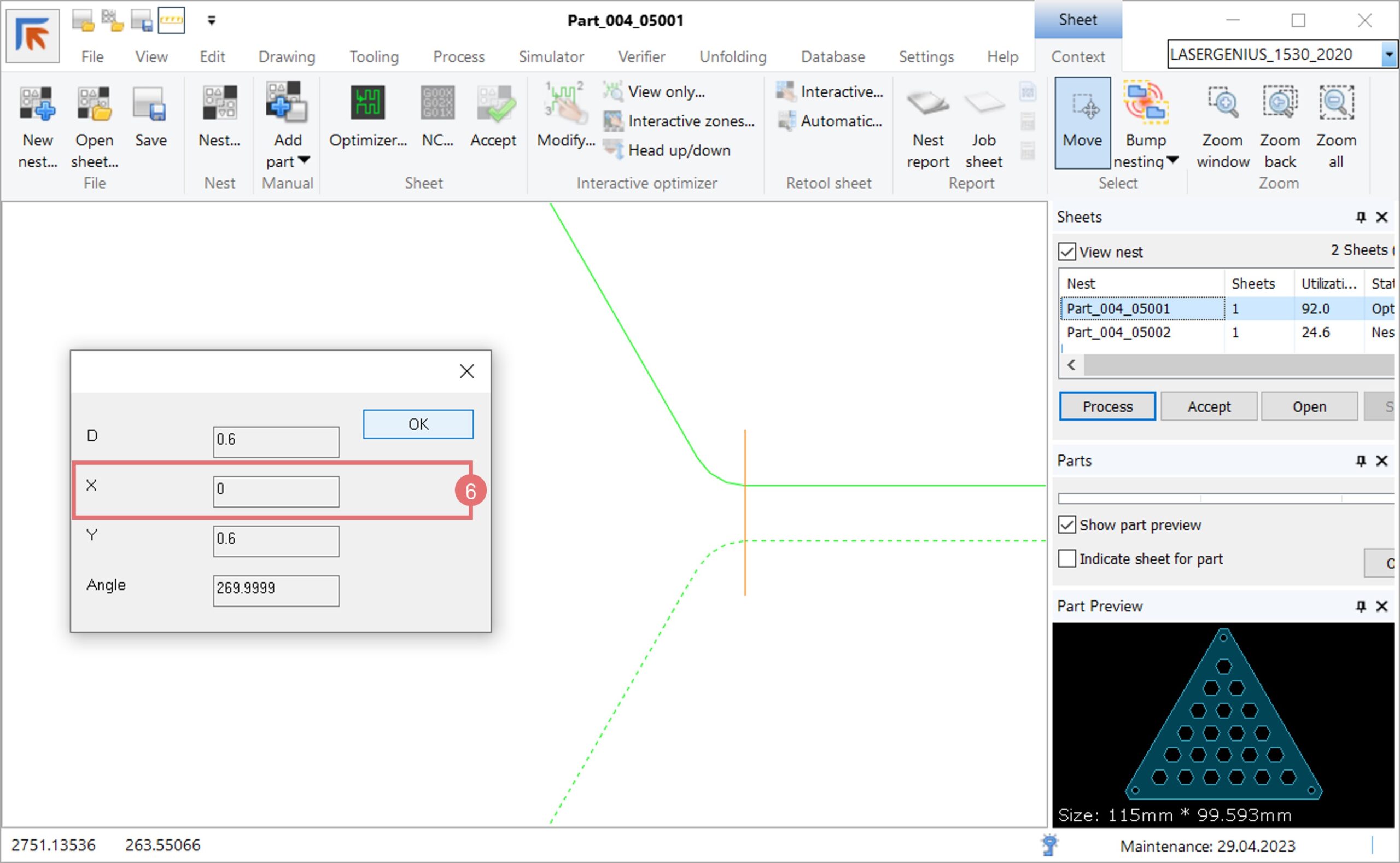
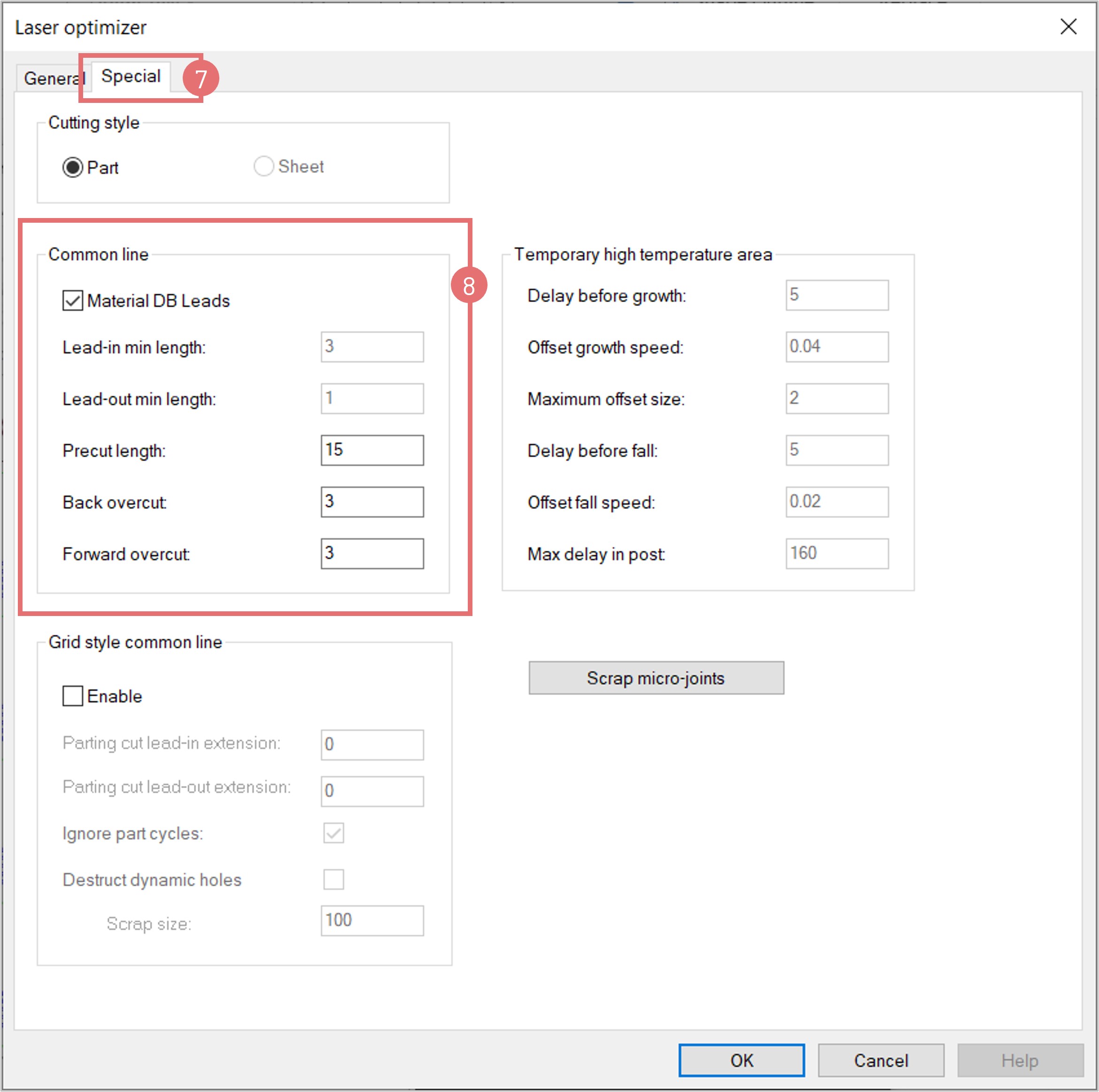
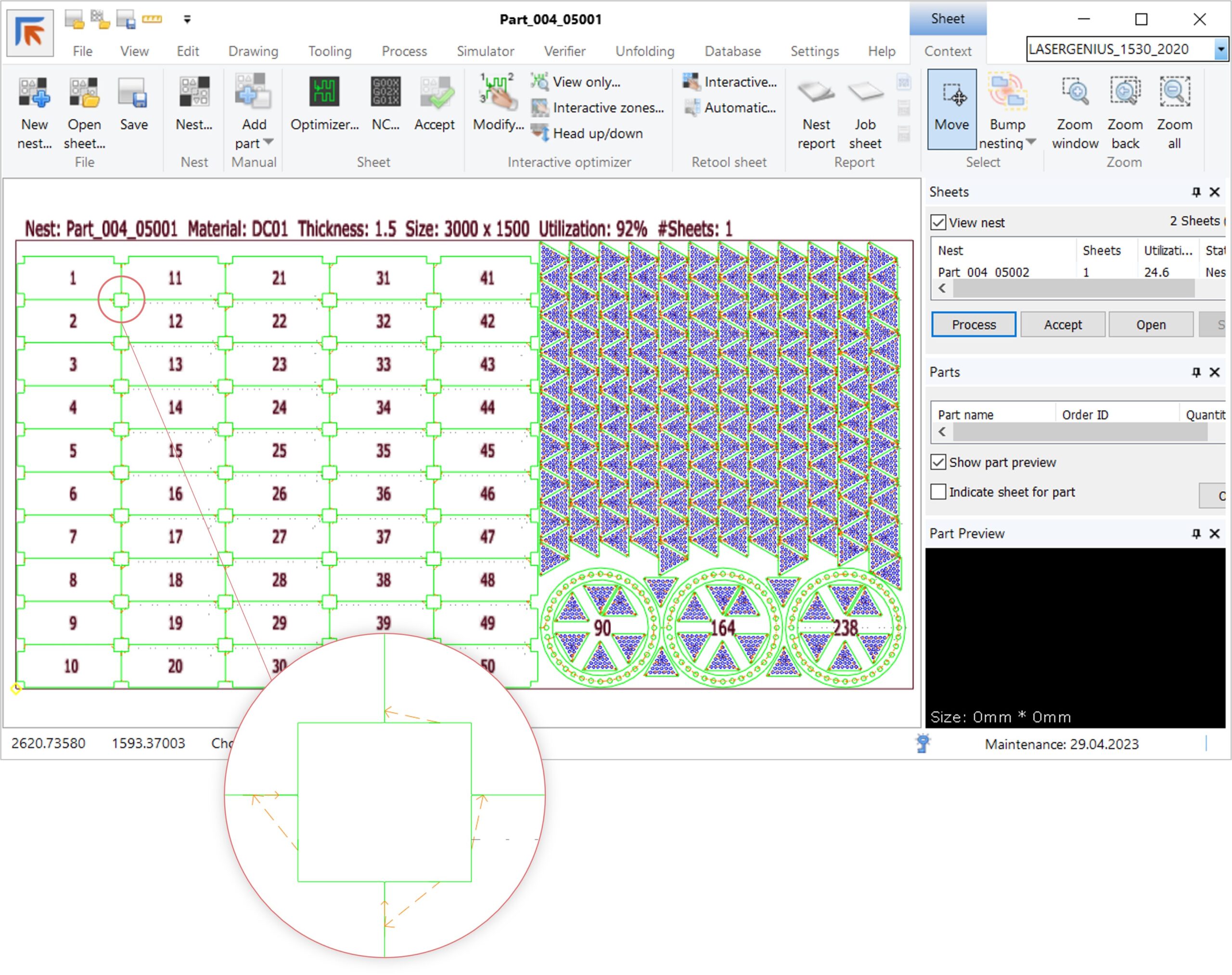
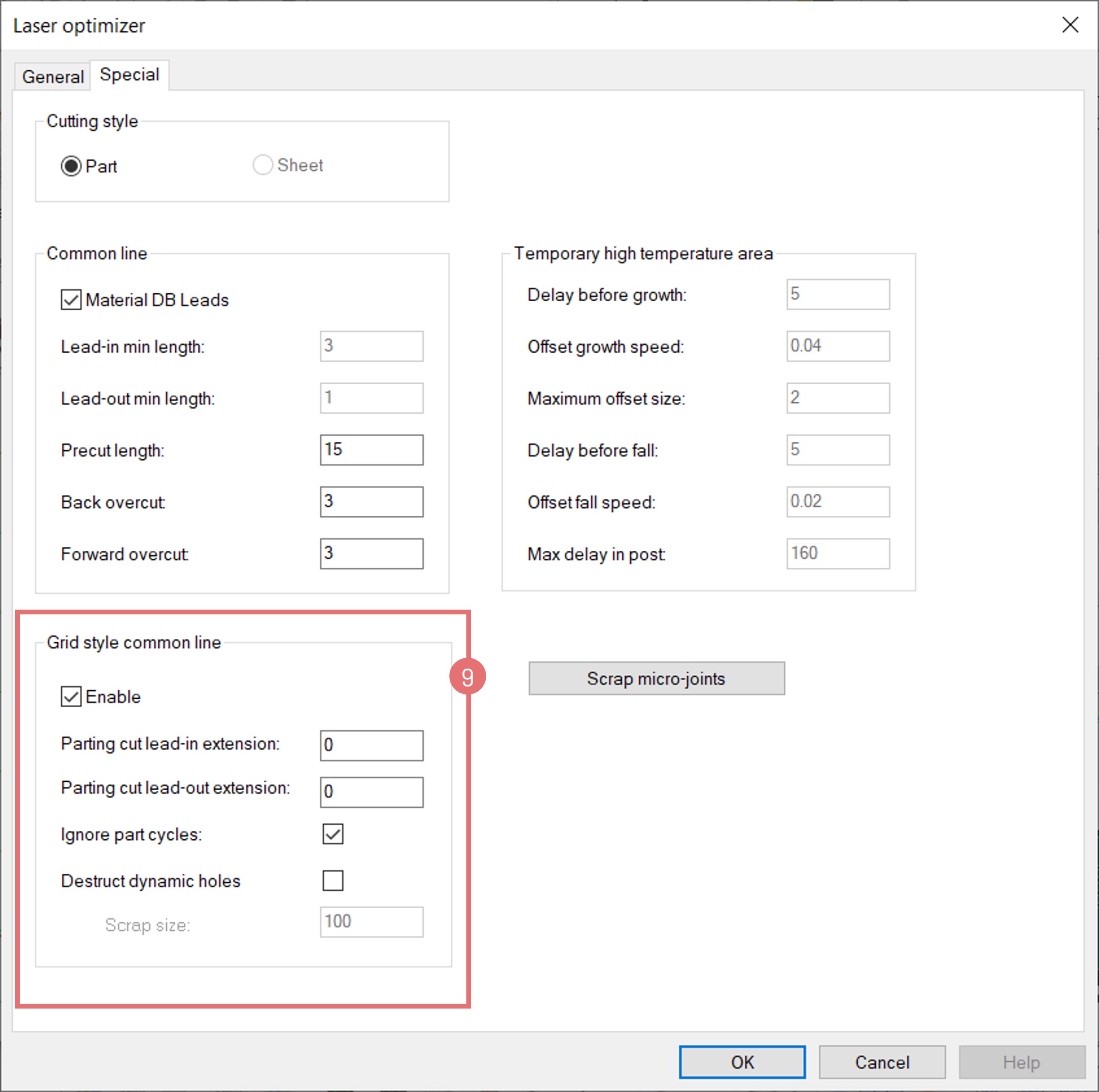
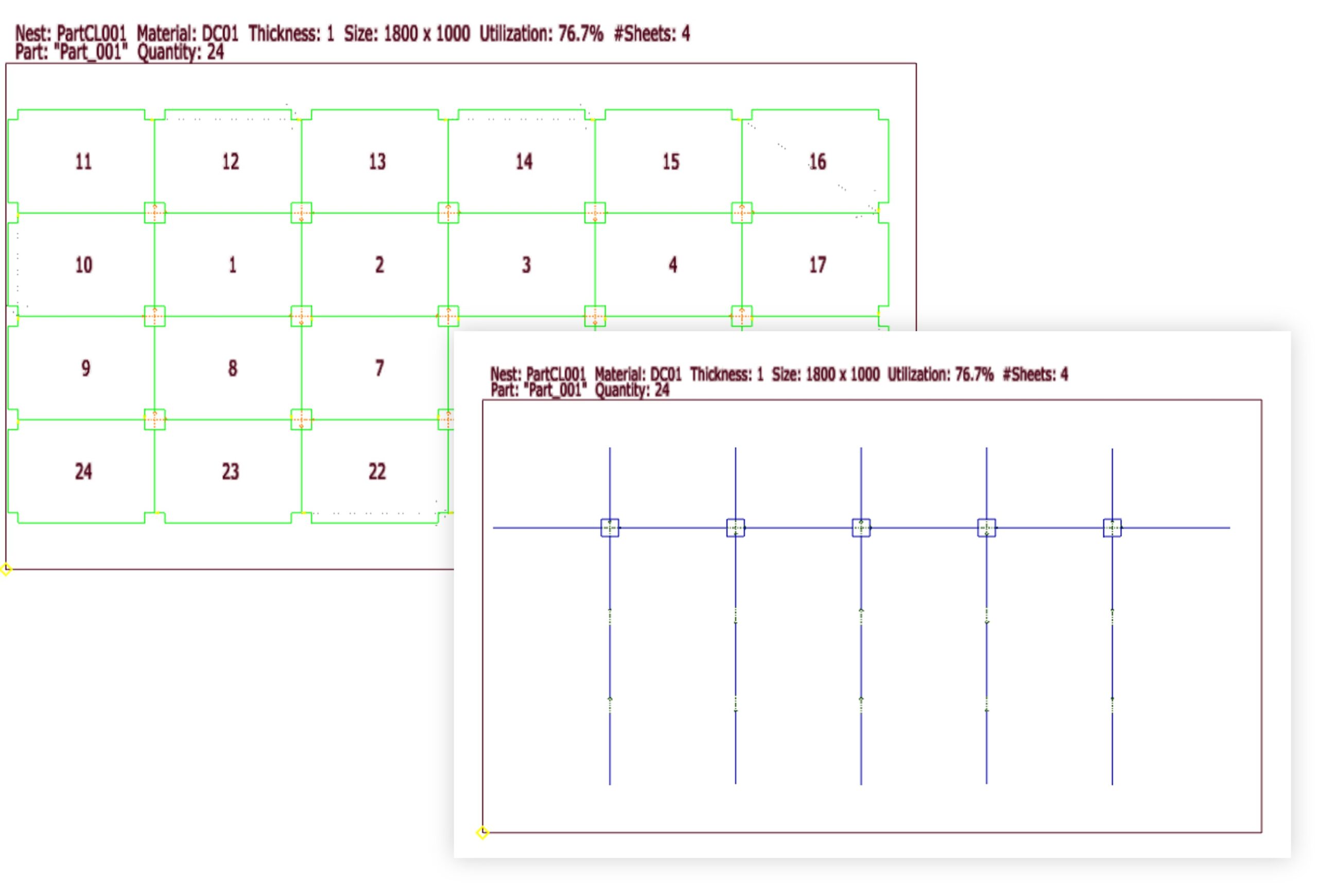
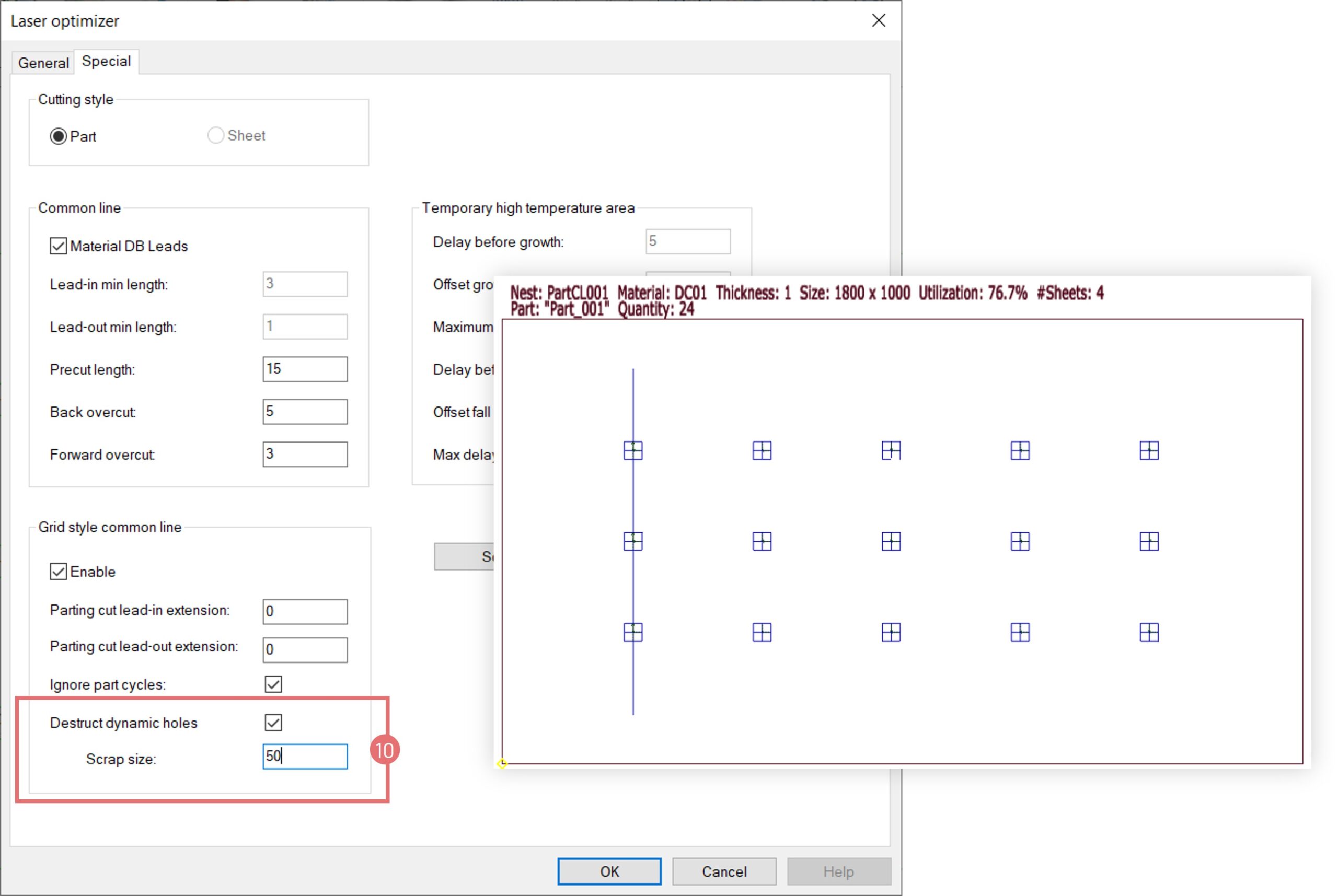
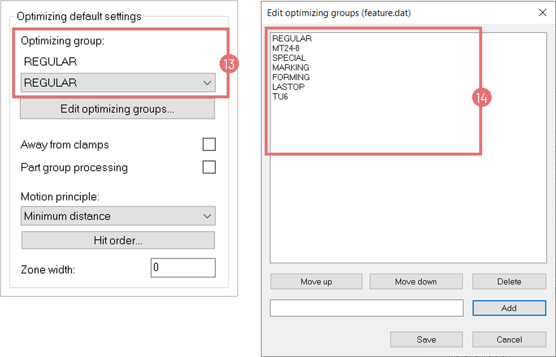
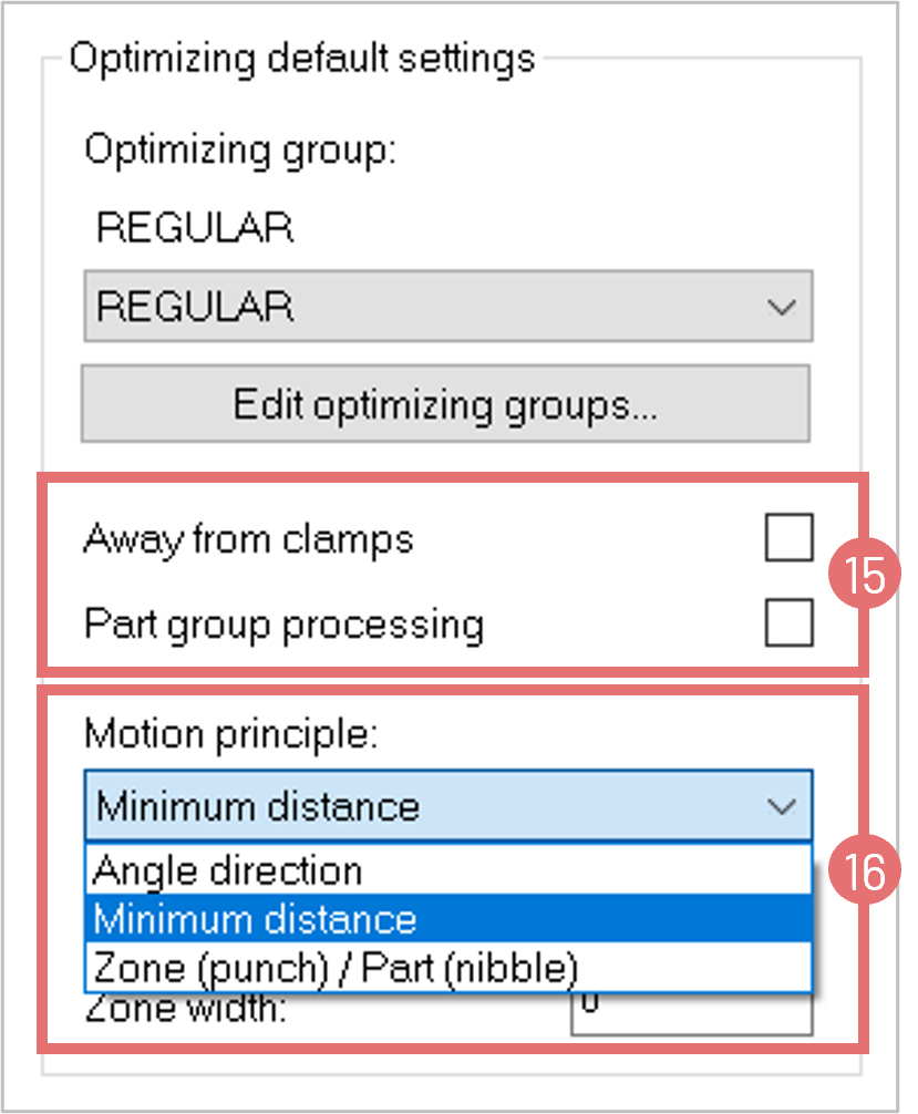
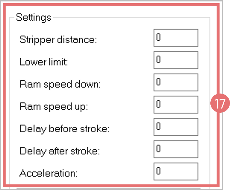
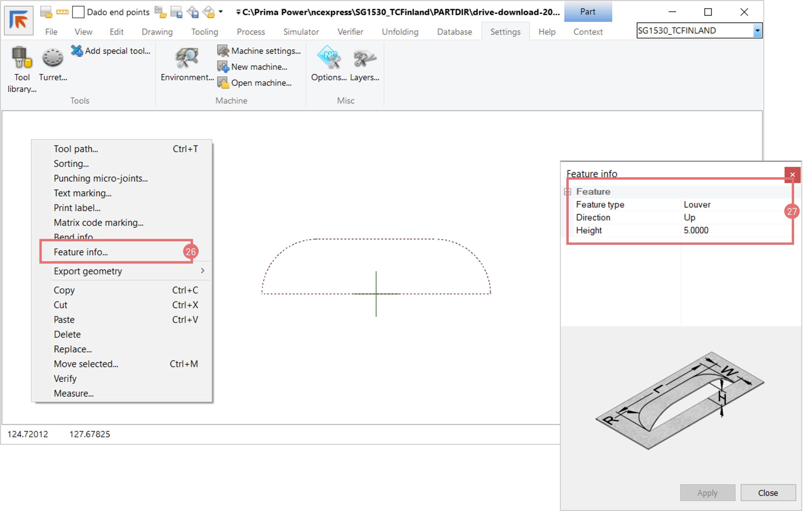
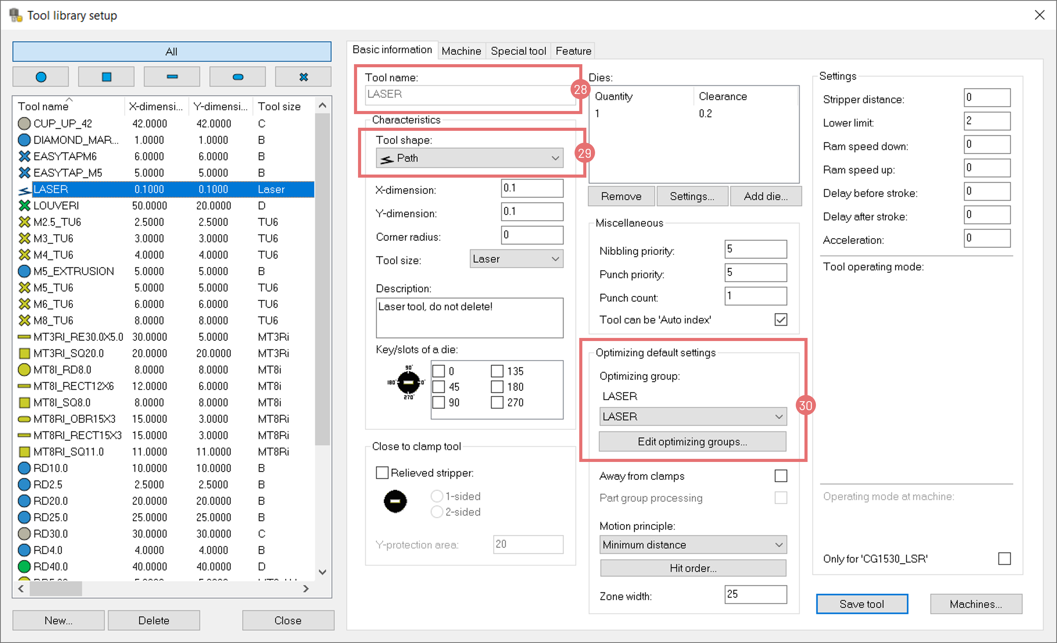
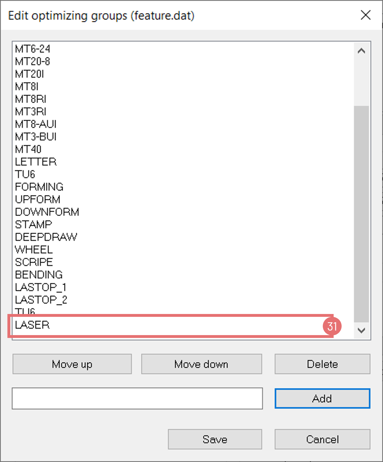
- Laser Optimizer Defaults: Save and restore optimization settings.
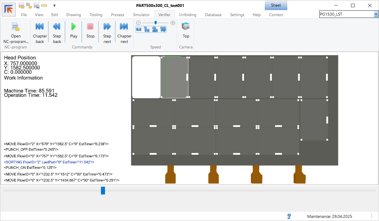
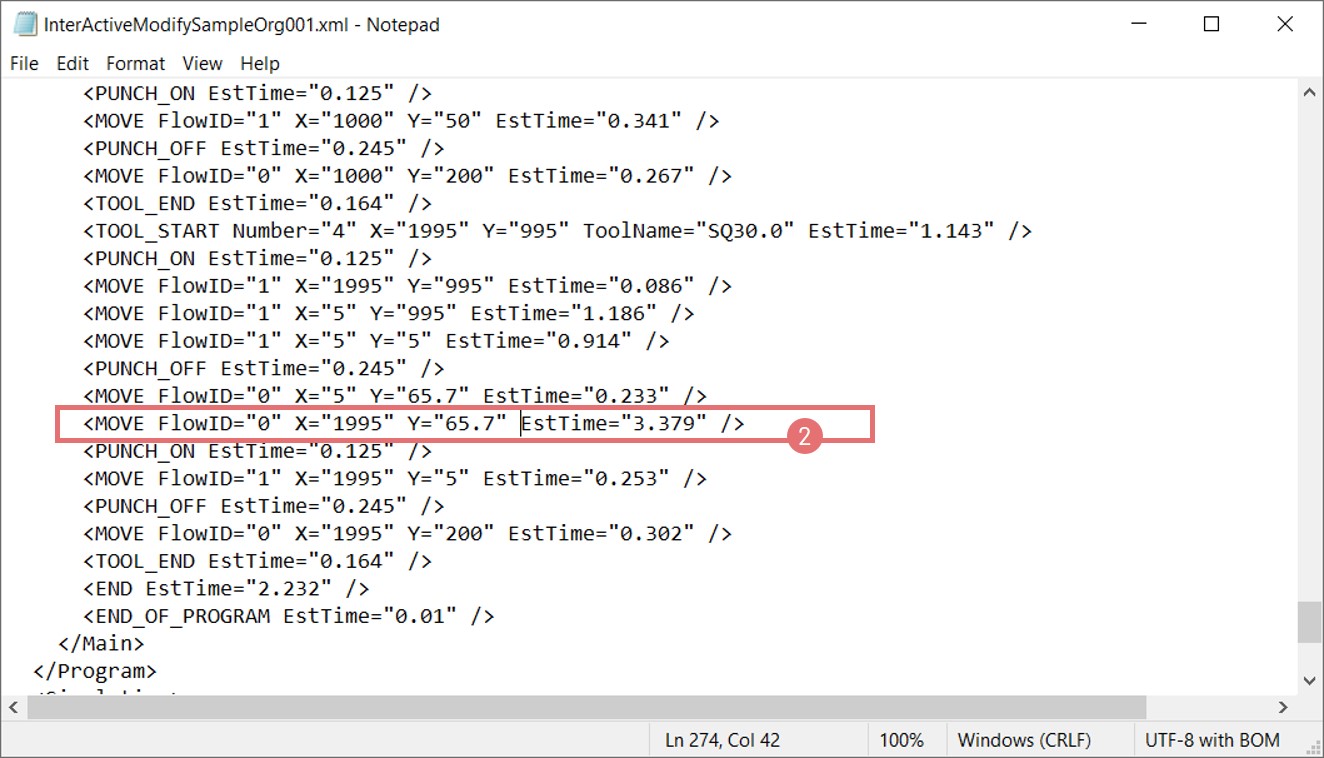
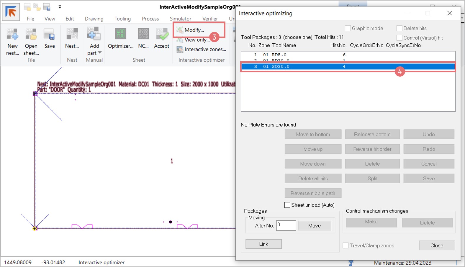
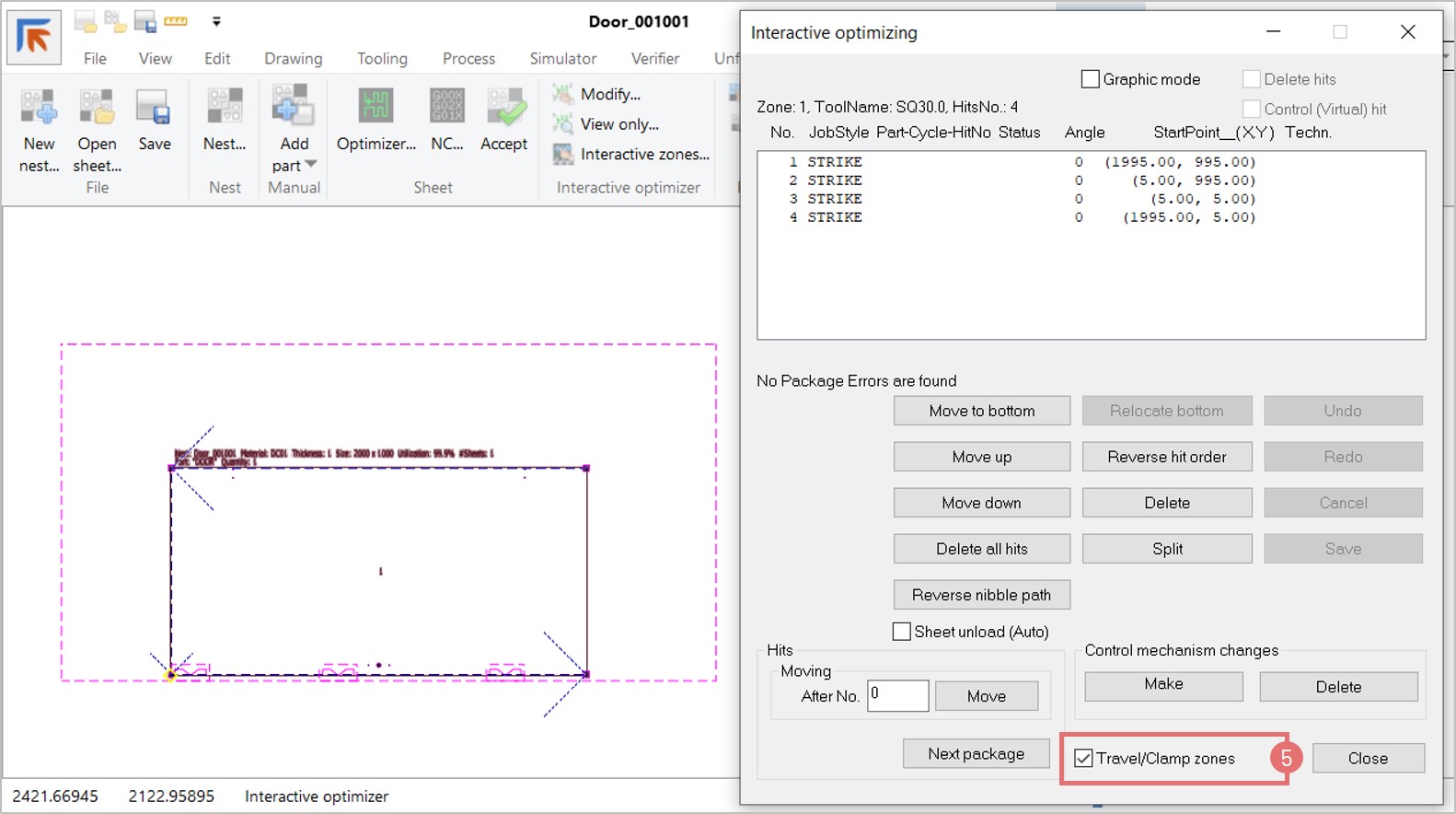
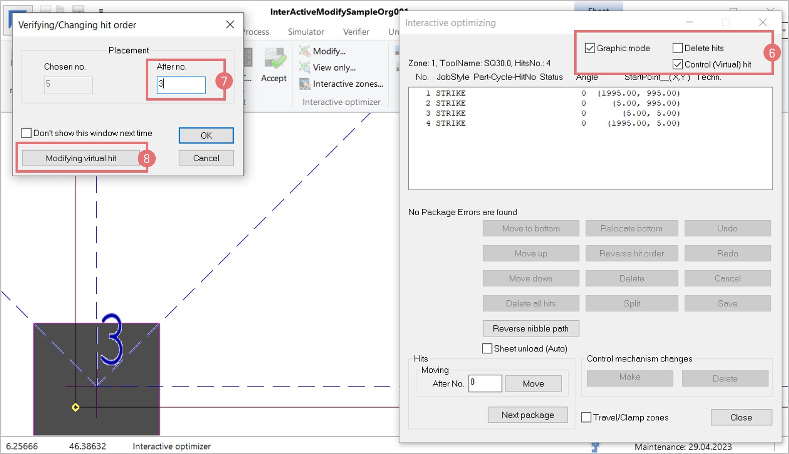
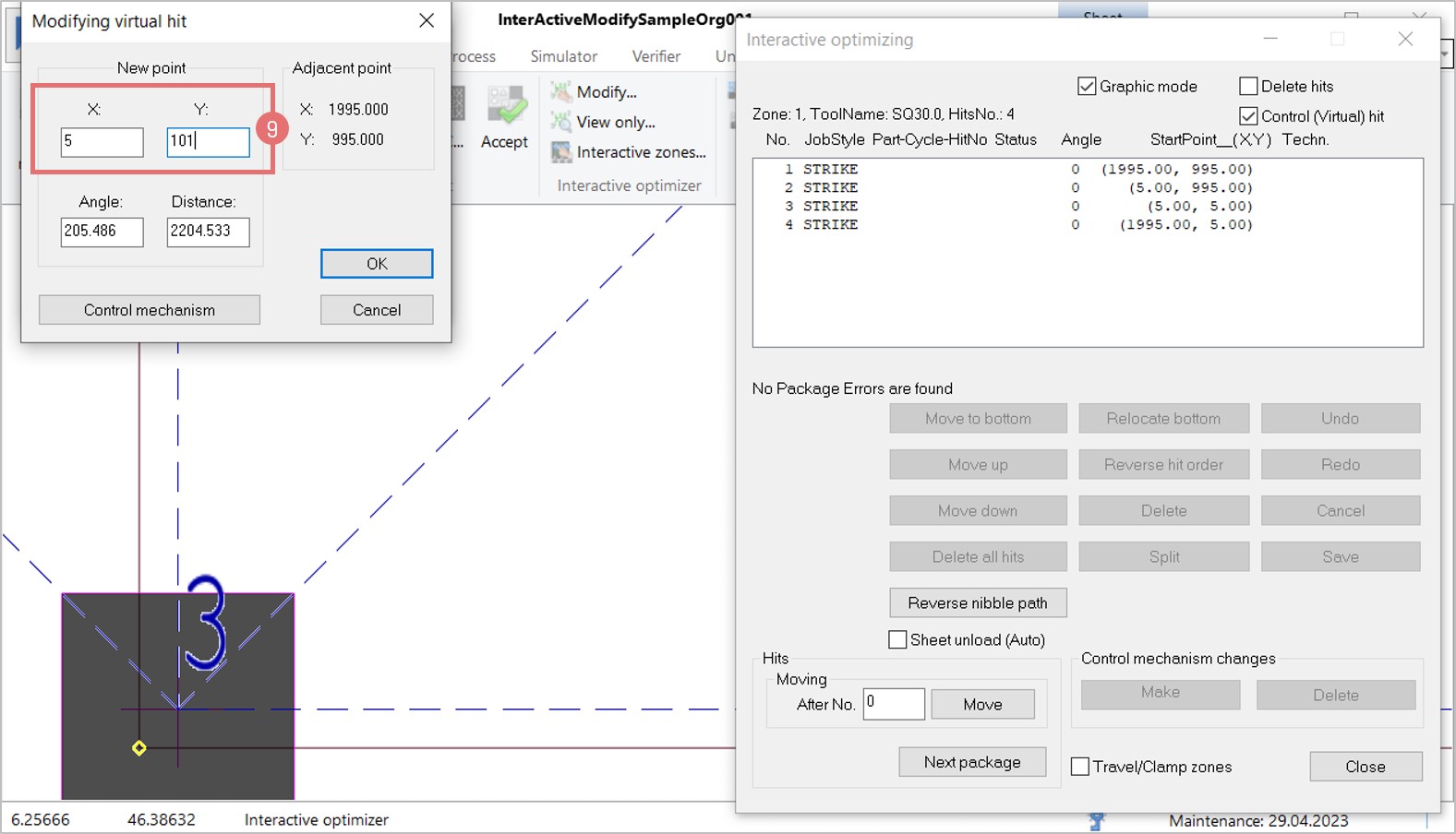
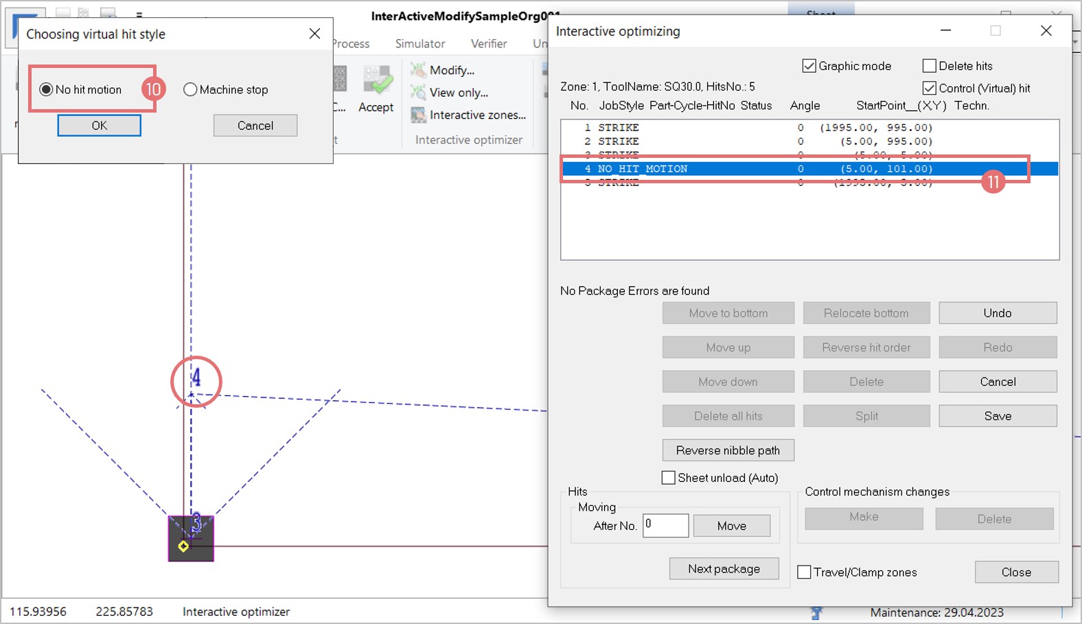
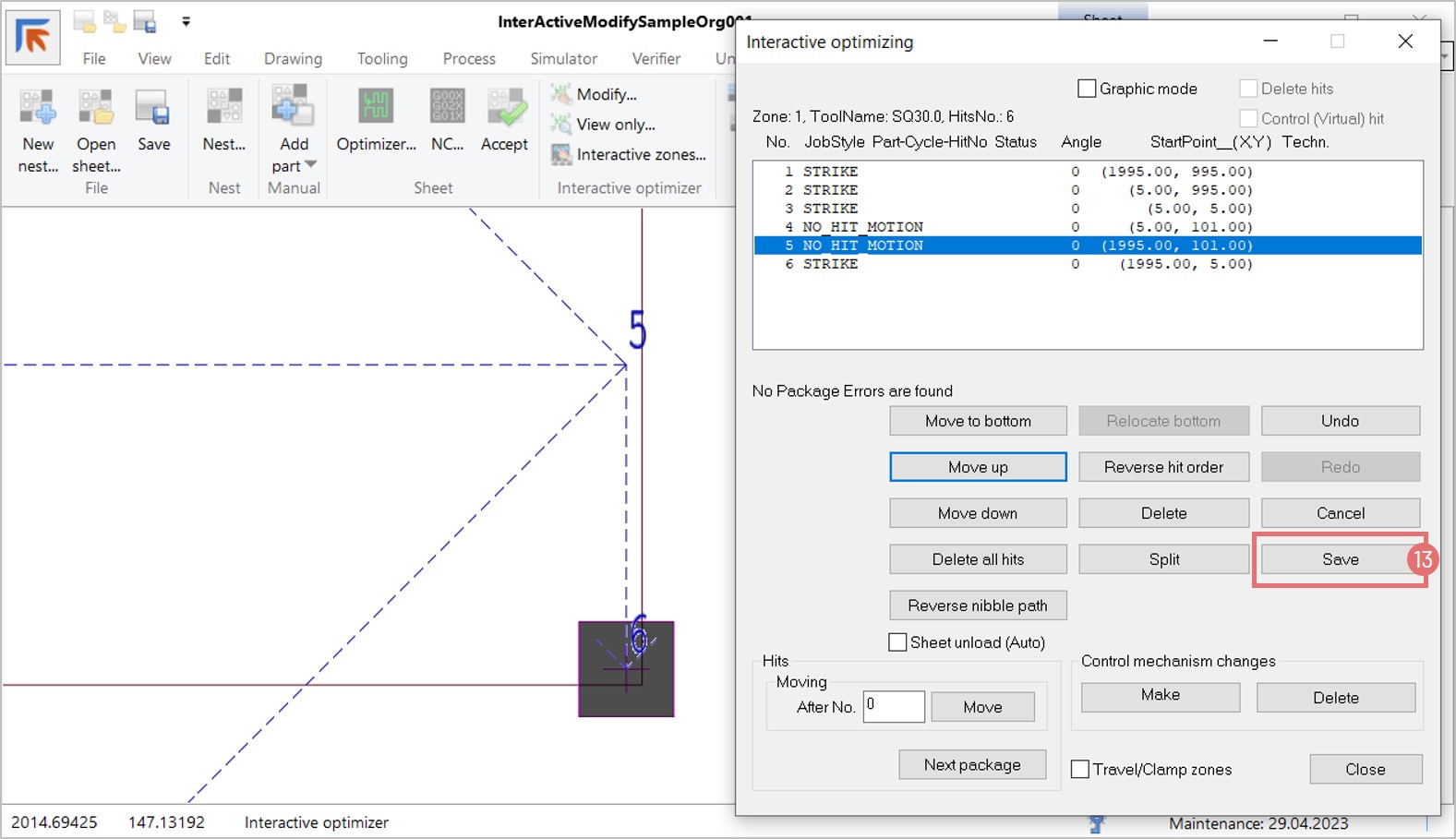
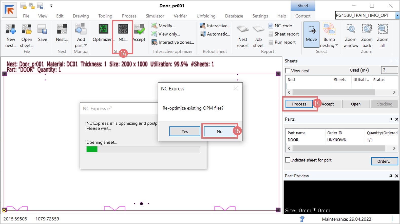
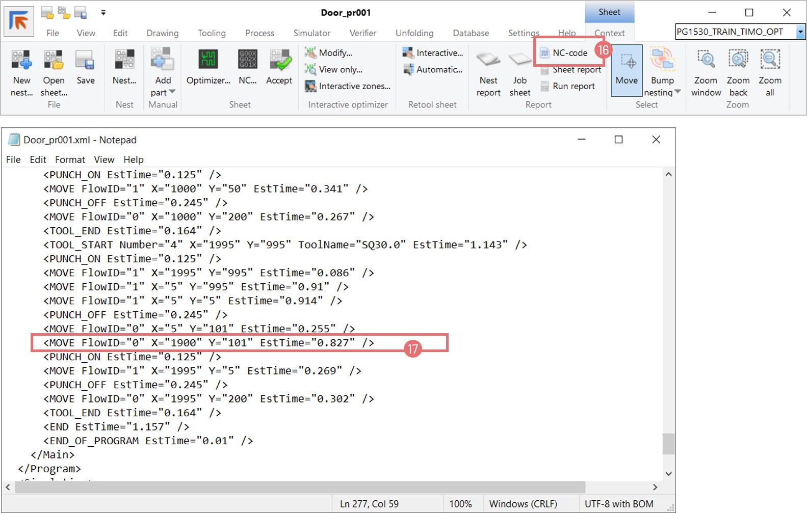
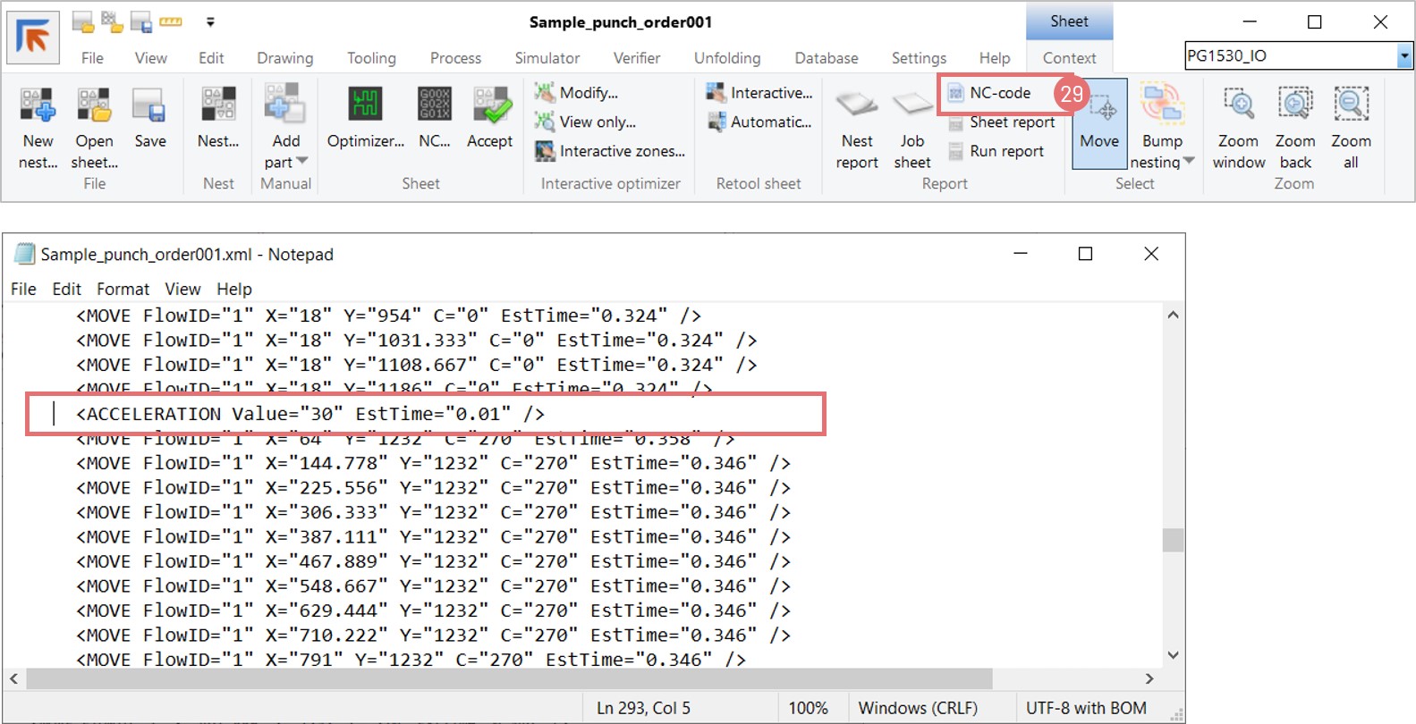
- No Hit Motion Support: Enables rapid skeleton traversal with virtual hits.
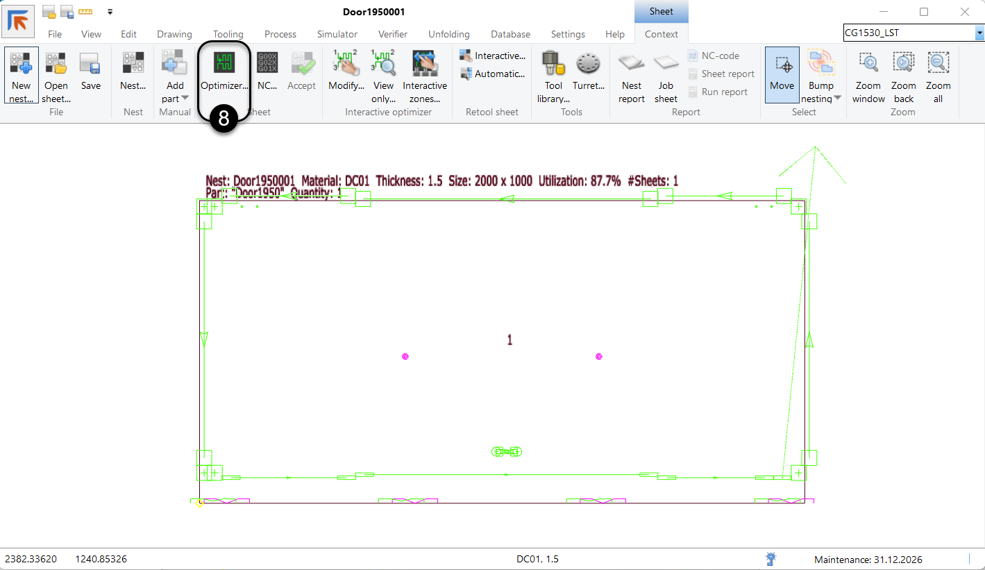
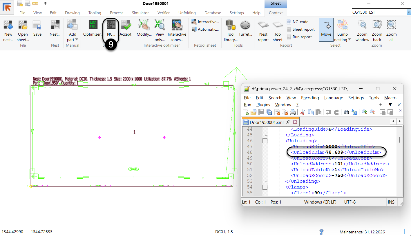
- Part Position Warnings: Alerts when parts are placed outside the sheet area.
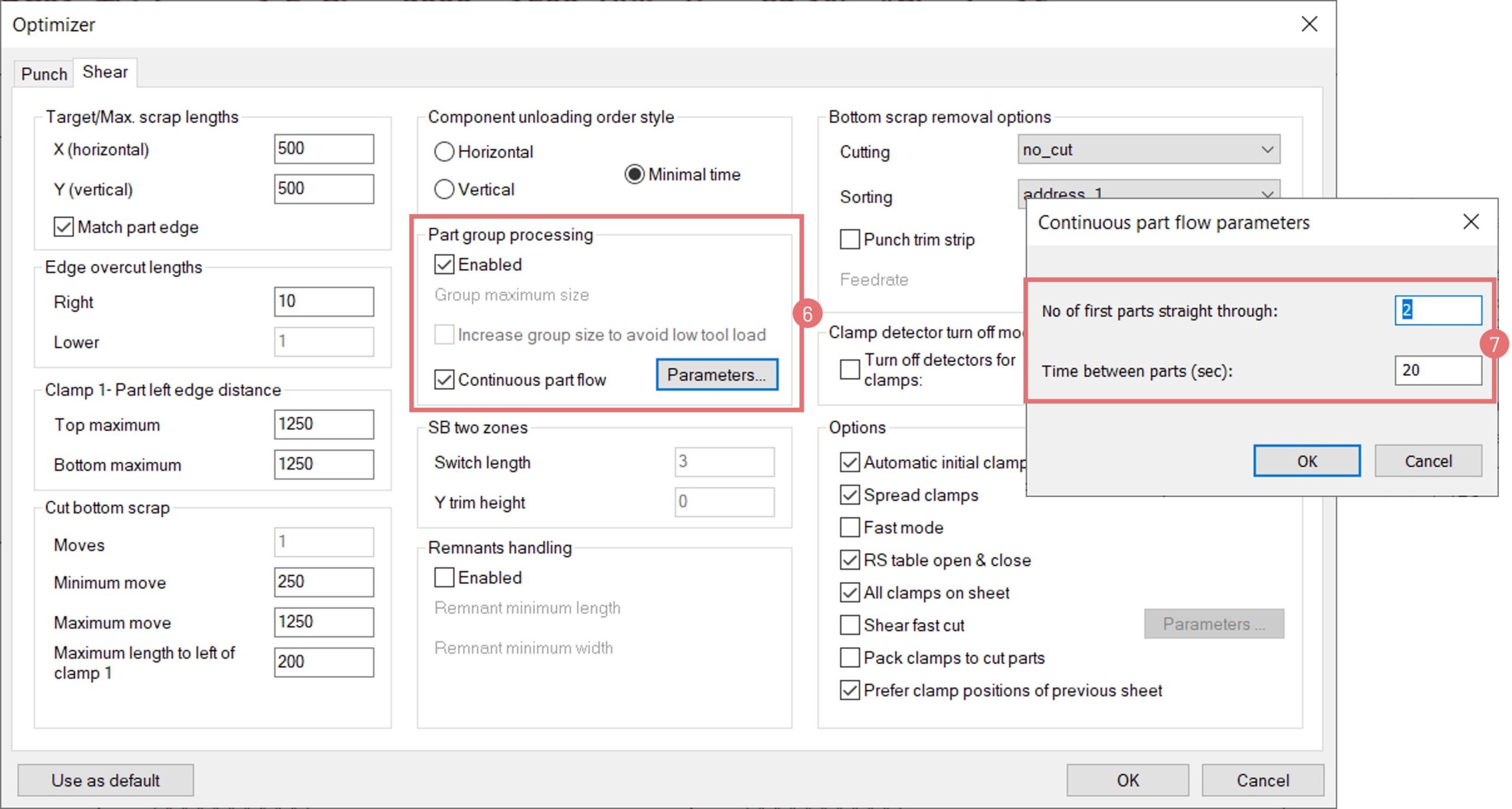
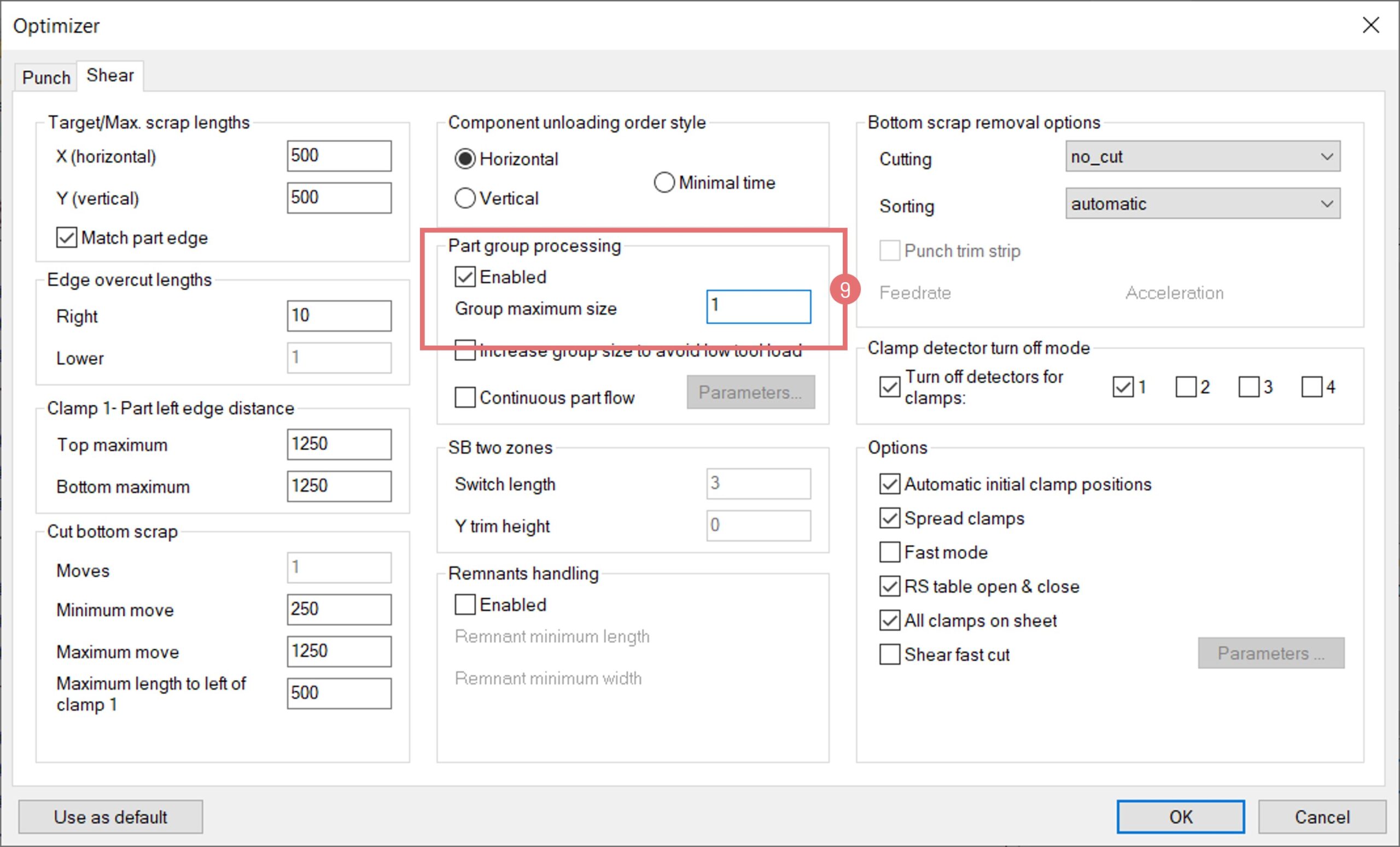
COMBI (Punch-Shear) Machines
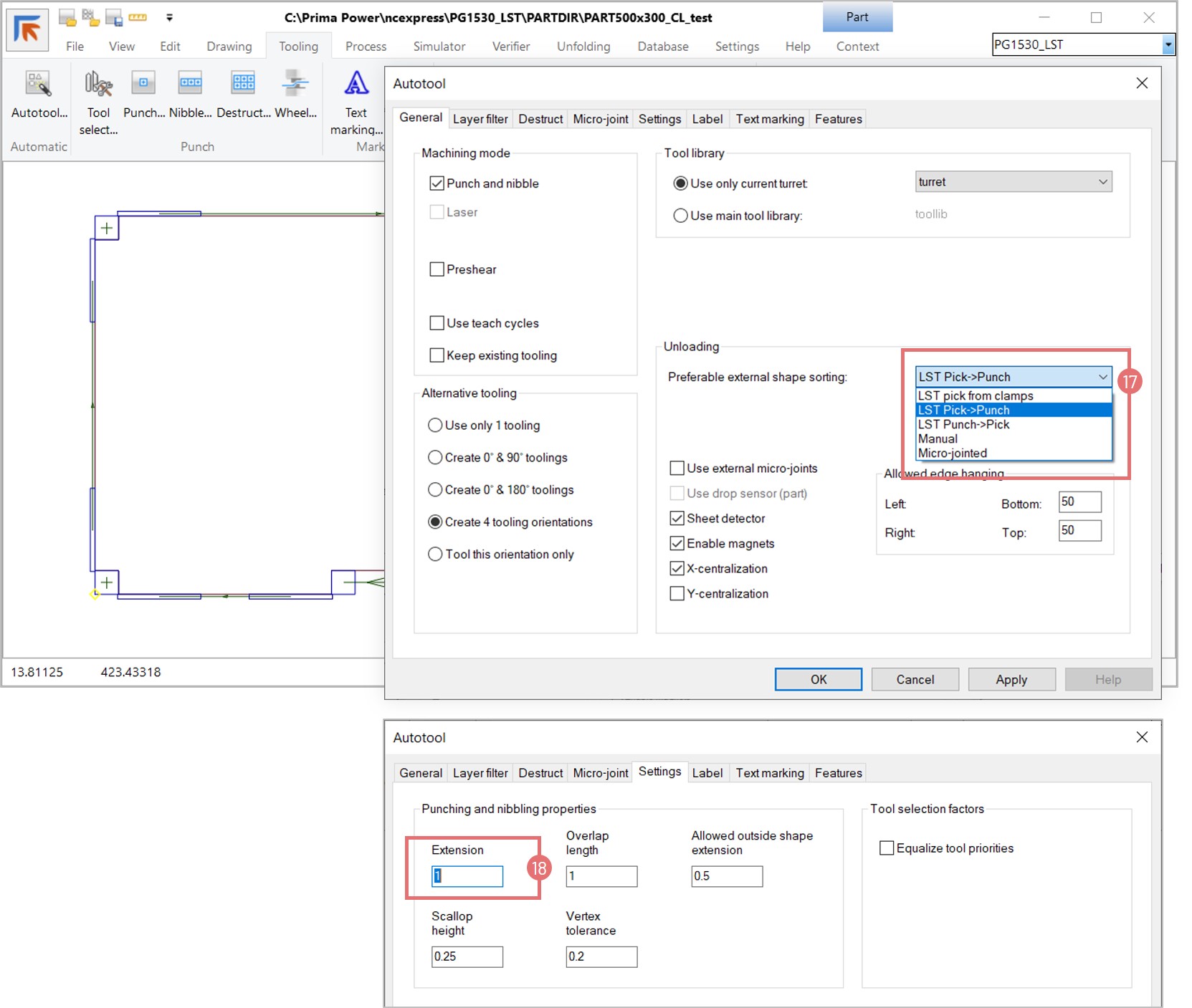
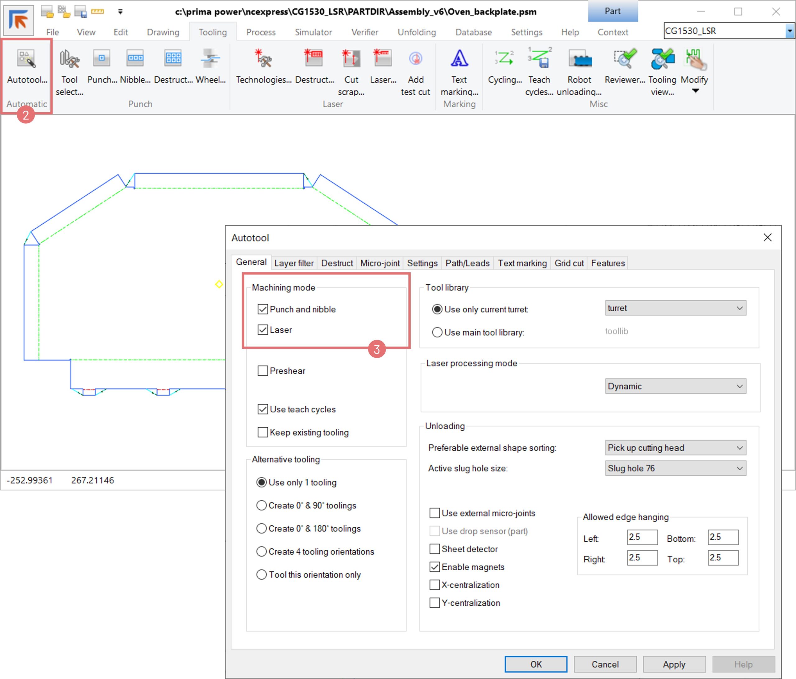
- Autotool for Selected Device: Tooling layers now tailored to specific sorting devices.
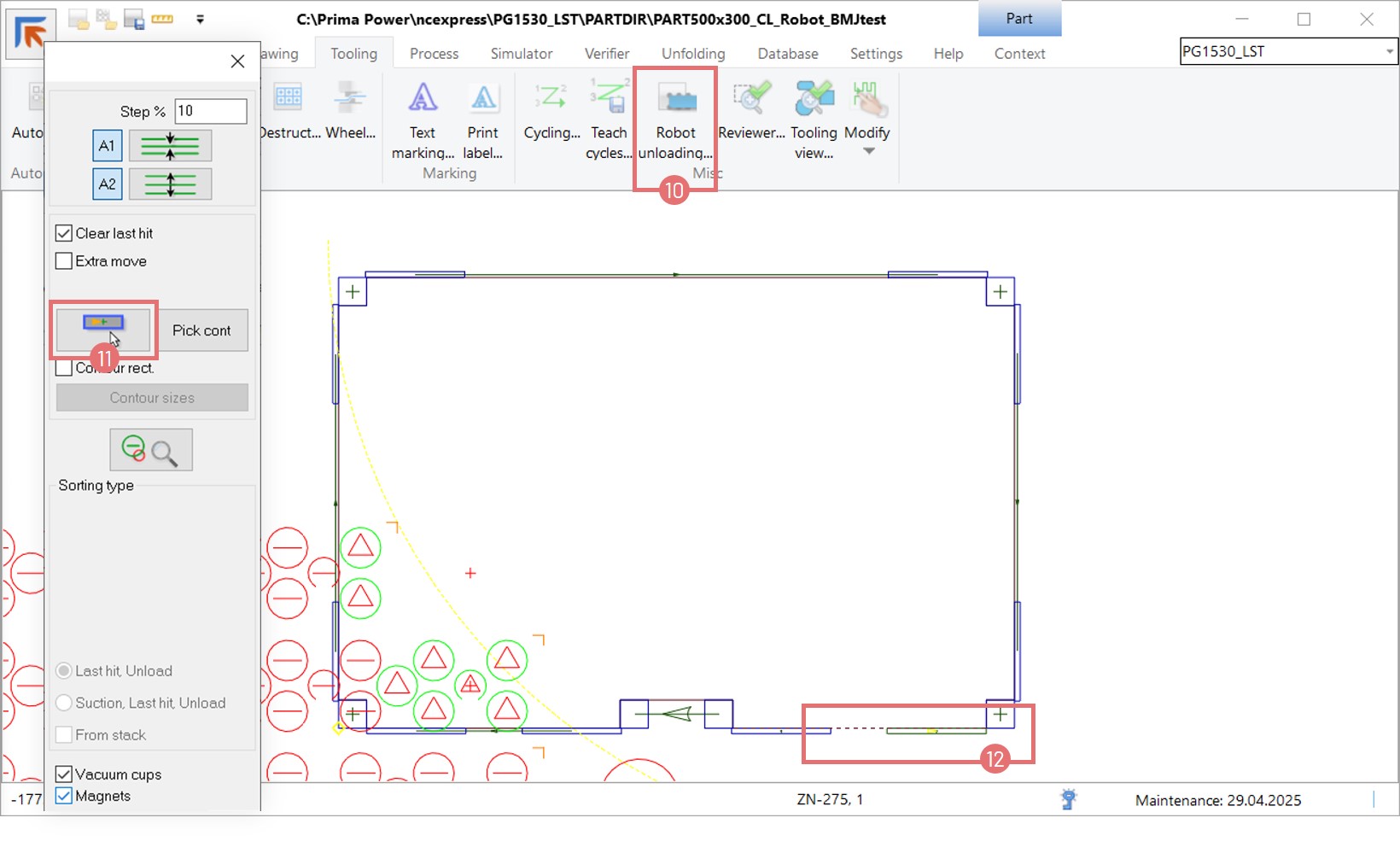
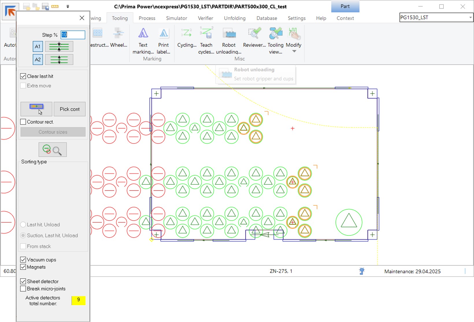
- Robot Placement with DSD: Improved logic for double sheet detection during robotic handling.
- Edge Destruct Parameters: New settings for punch overcut distances.
COMBI (Laser-Punch) Machines
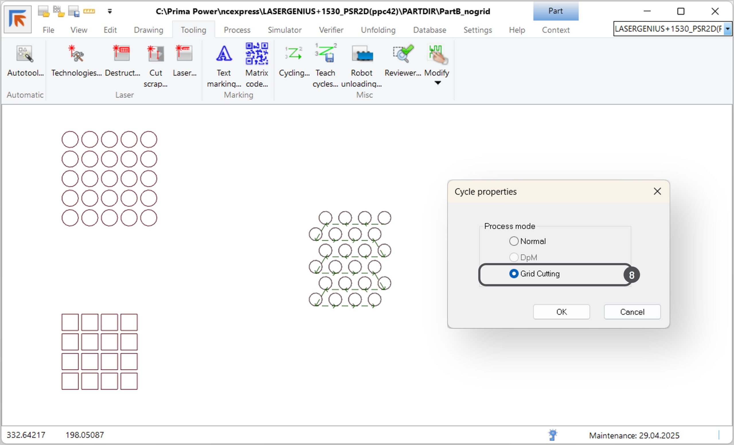
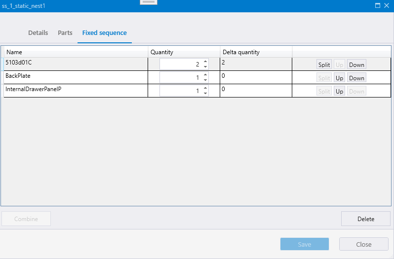
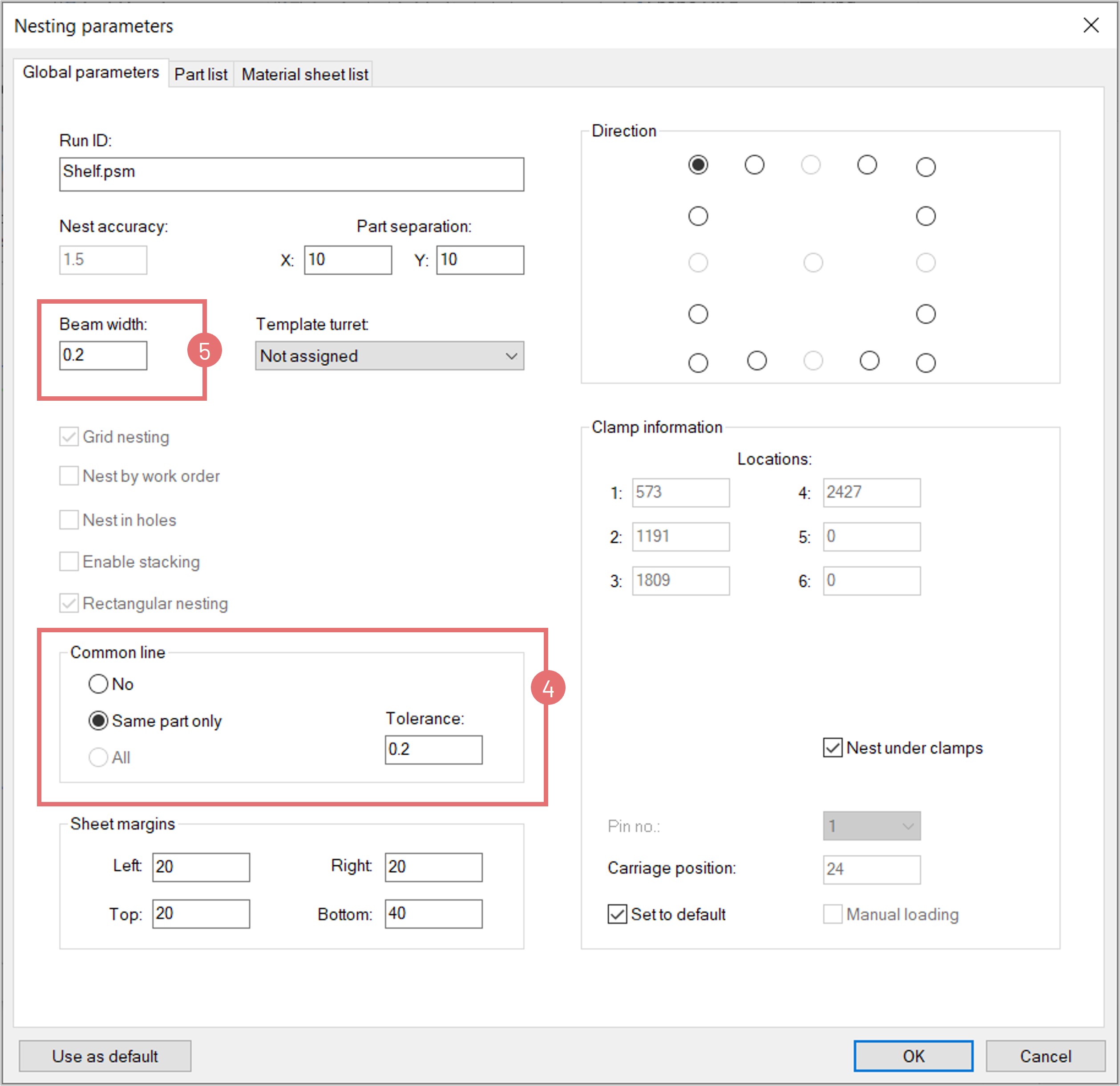
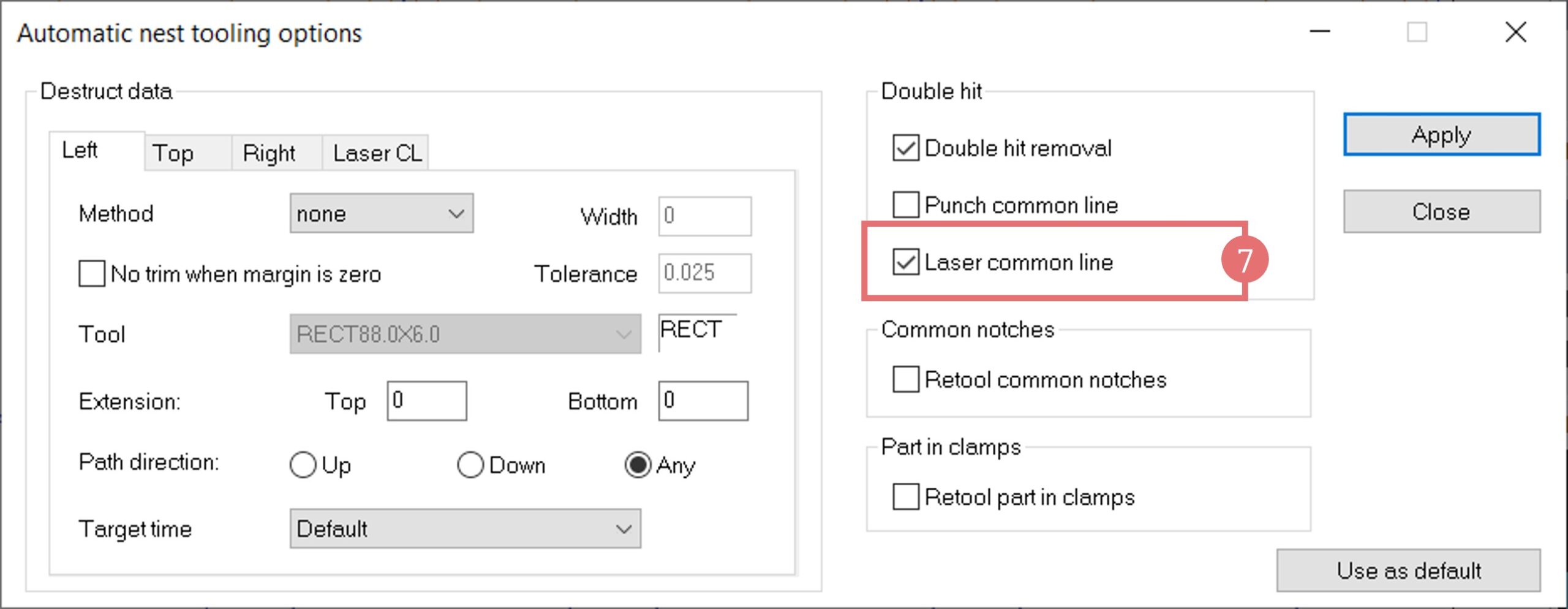
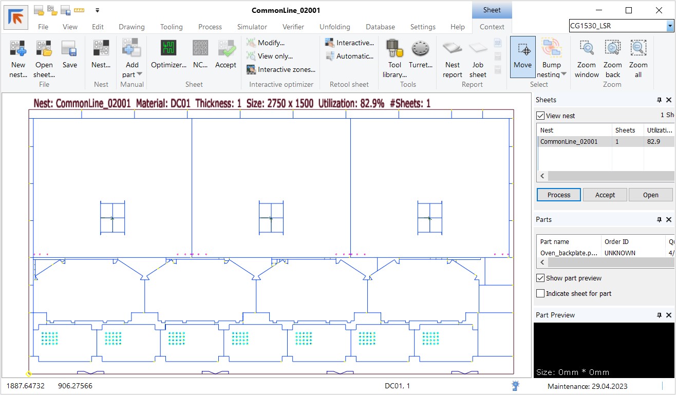
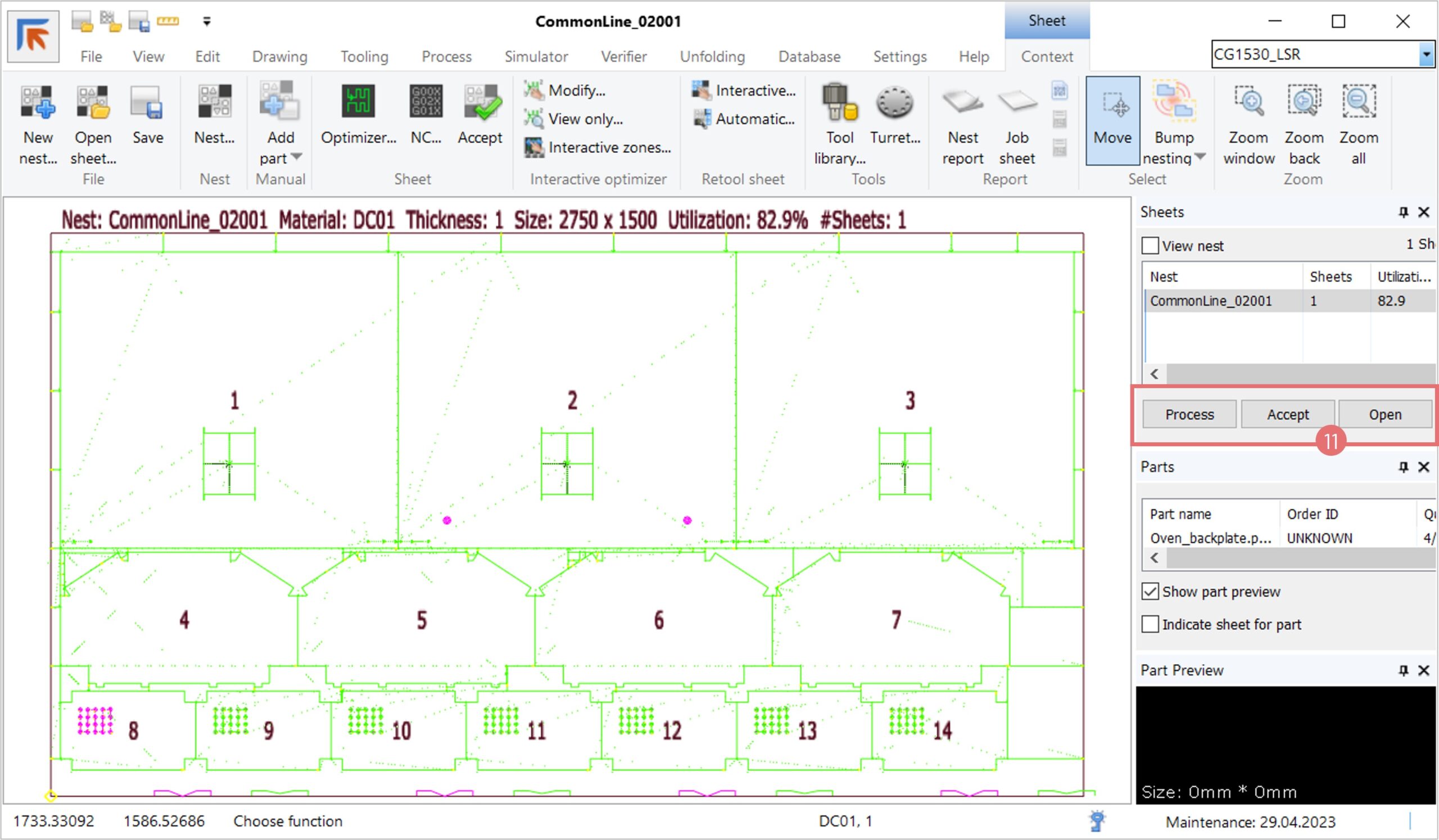
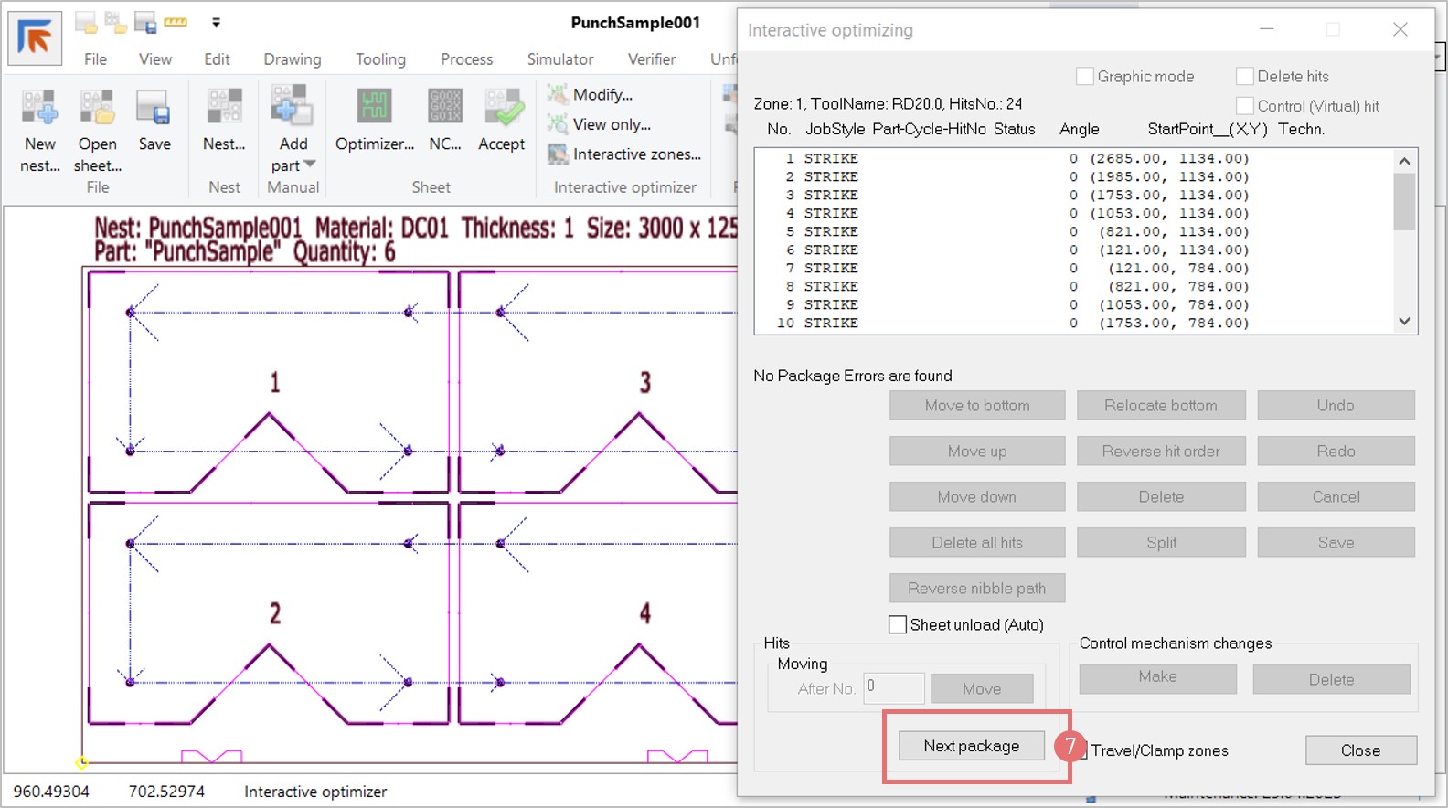
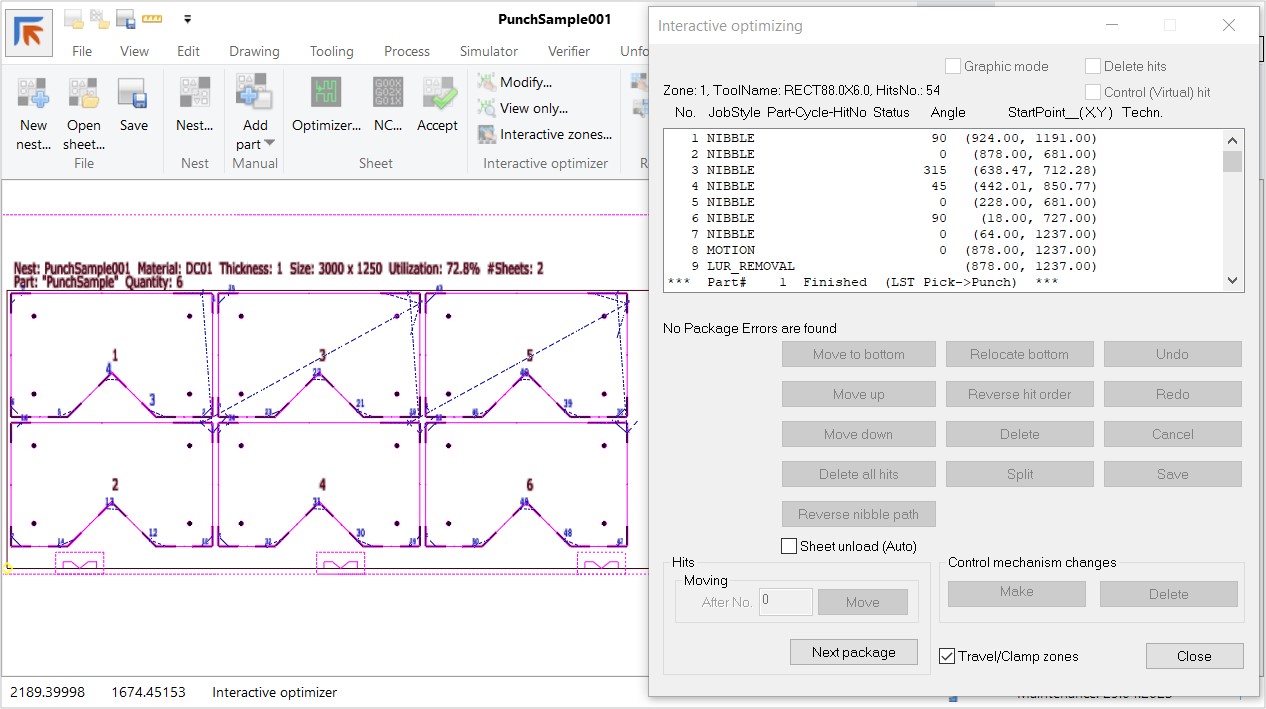
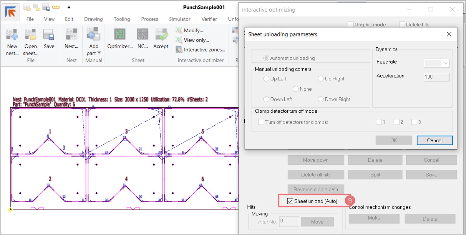
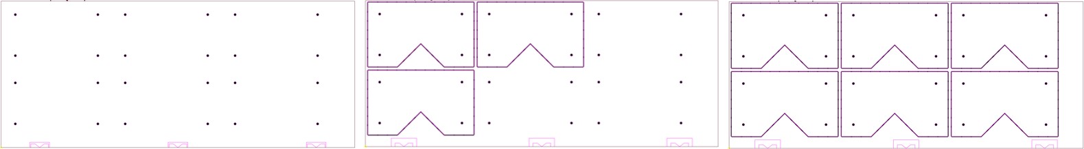
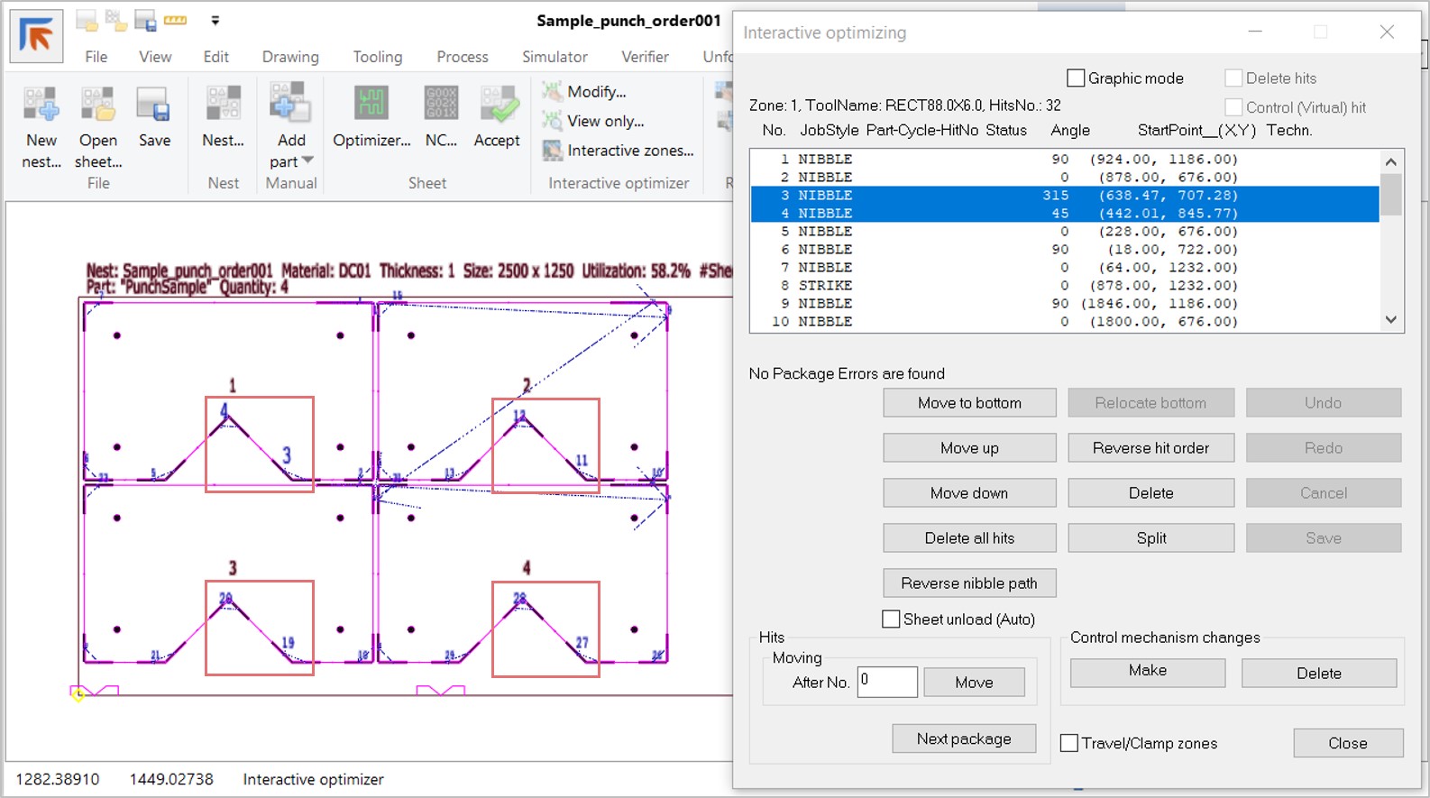
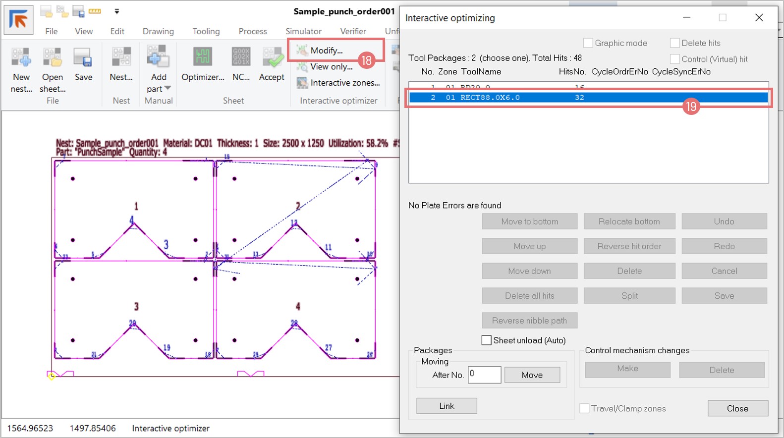
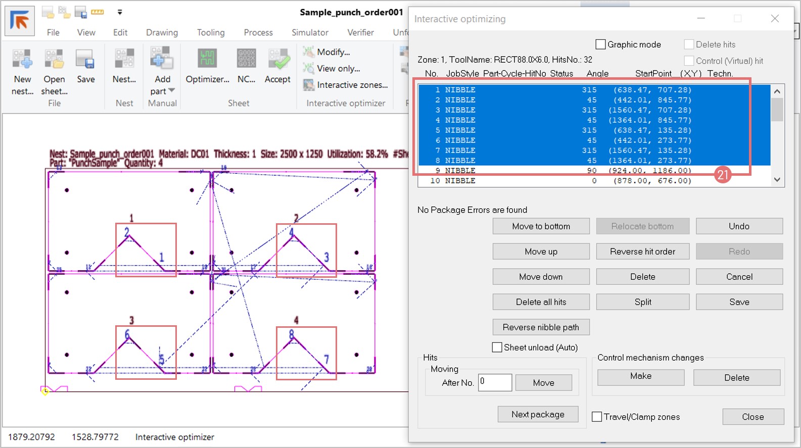
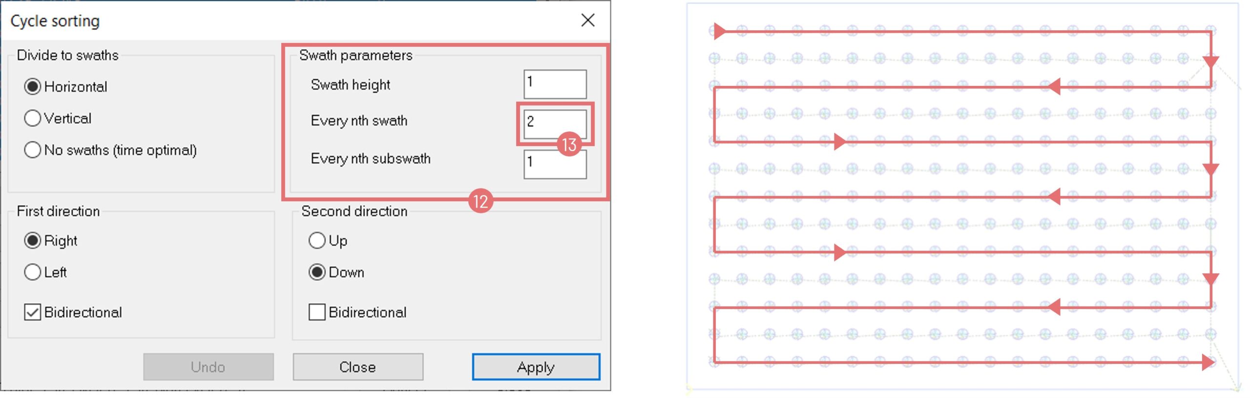
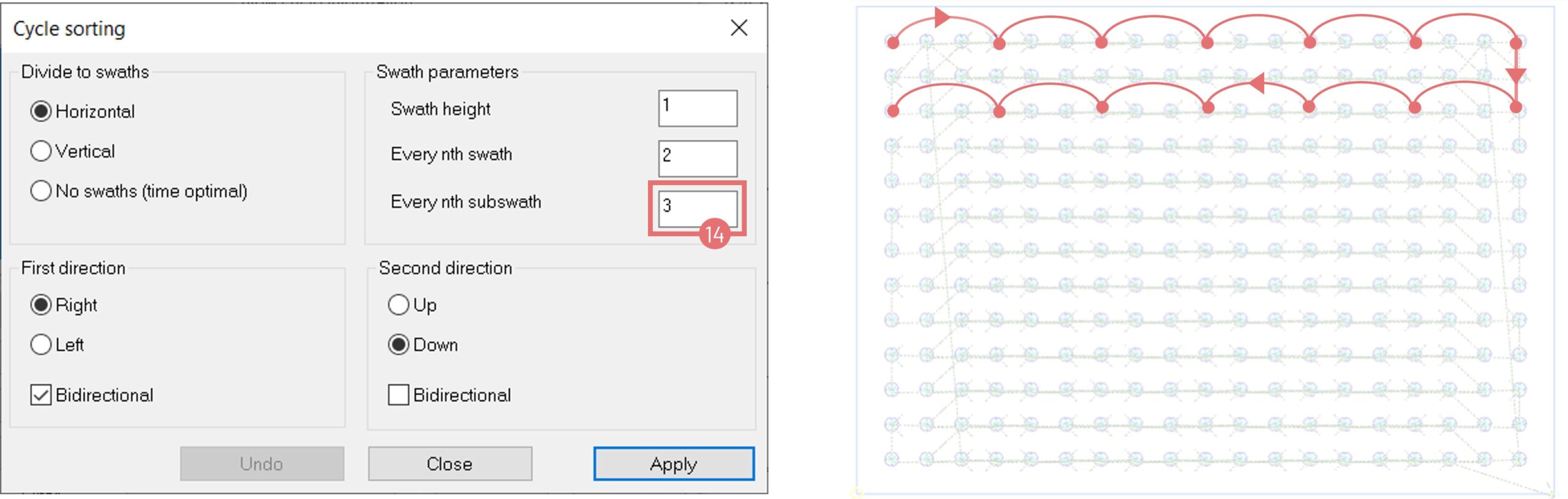
- Release Sequence Support: Now available for laser-punch machines, improving part flow and nesting control.
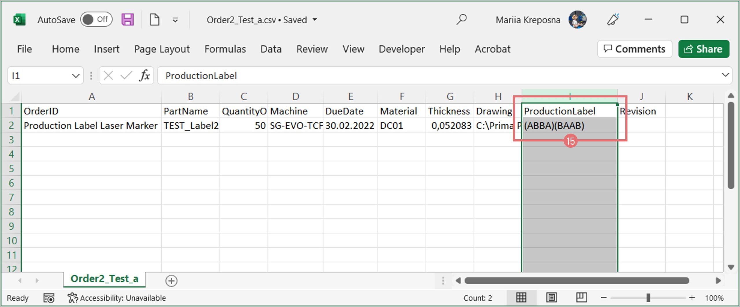
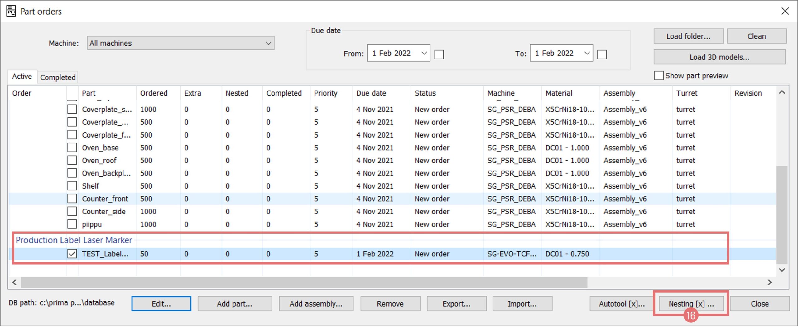
Usability & Database Improvements
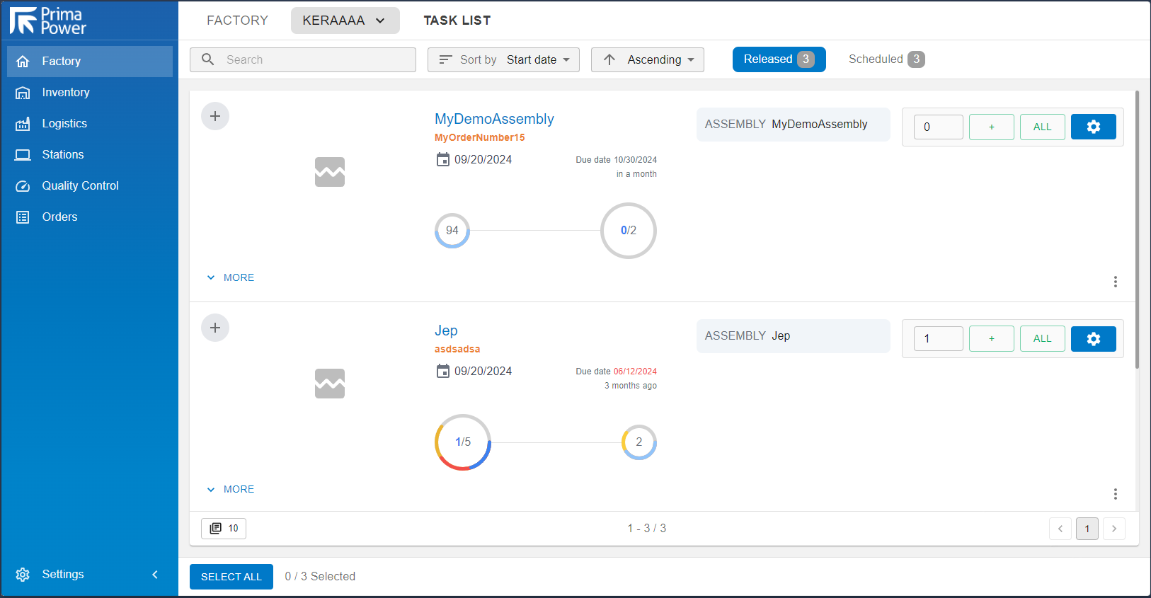
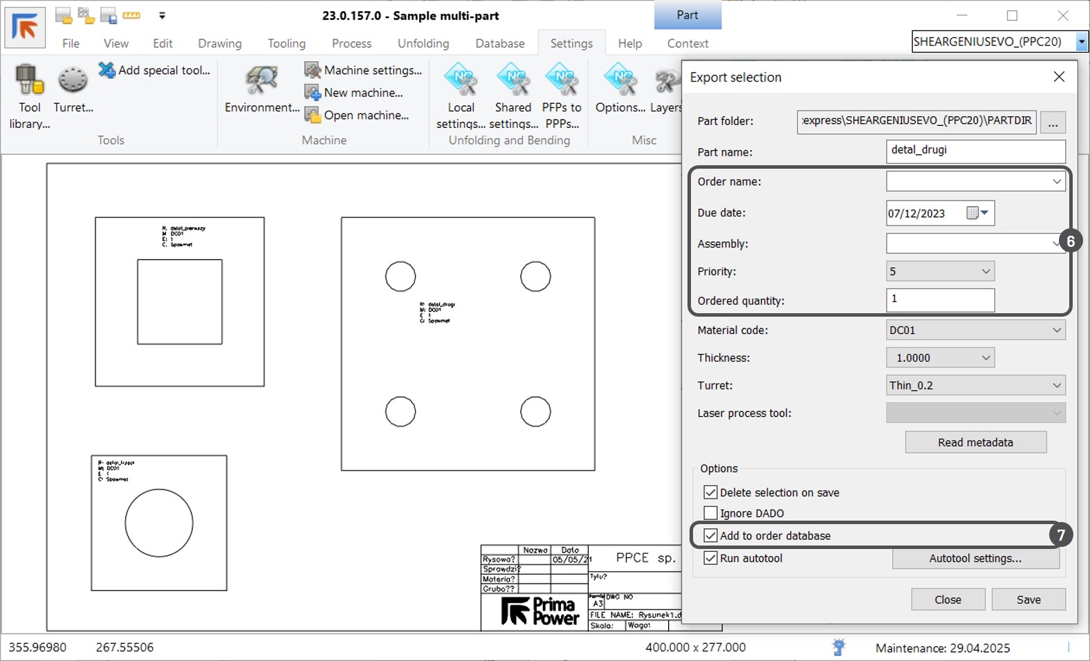
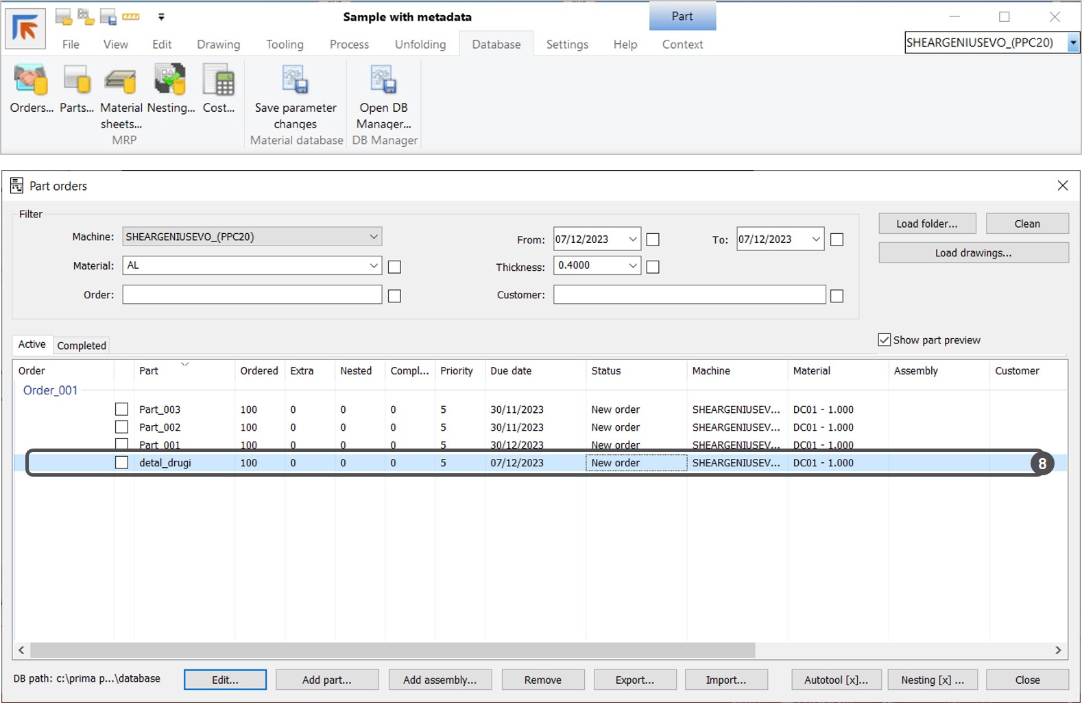
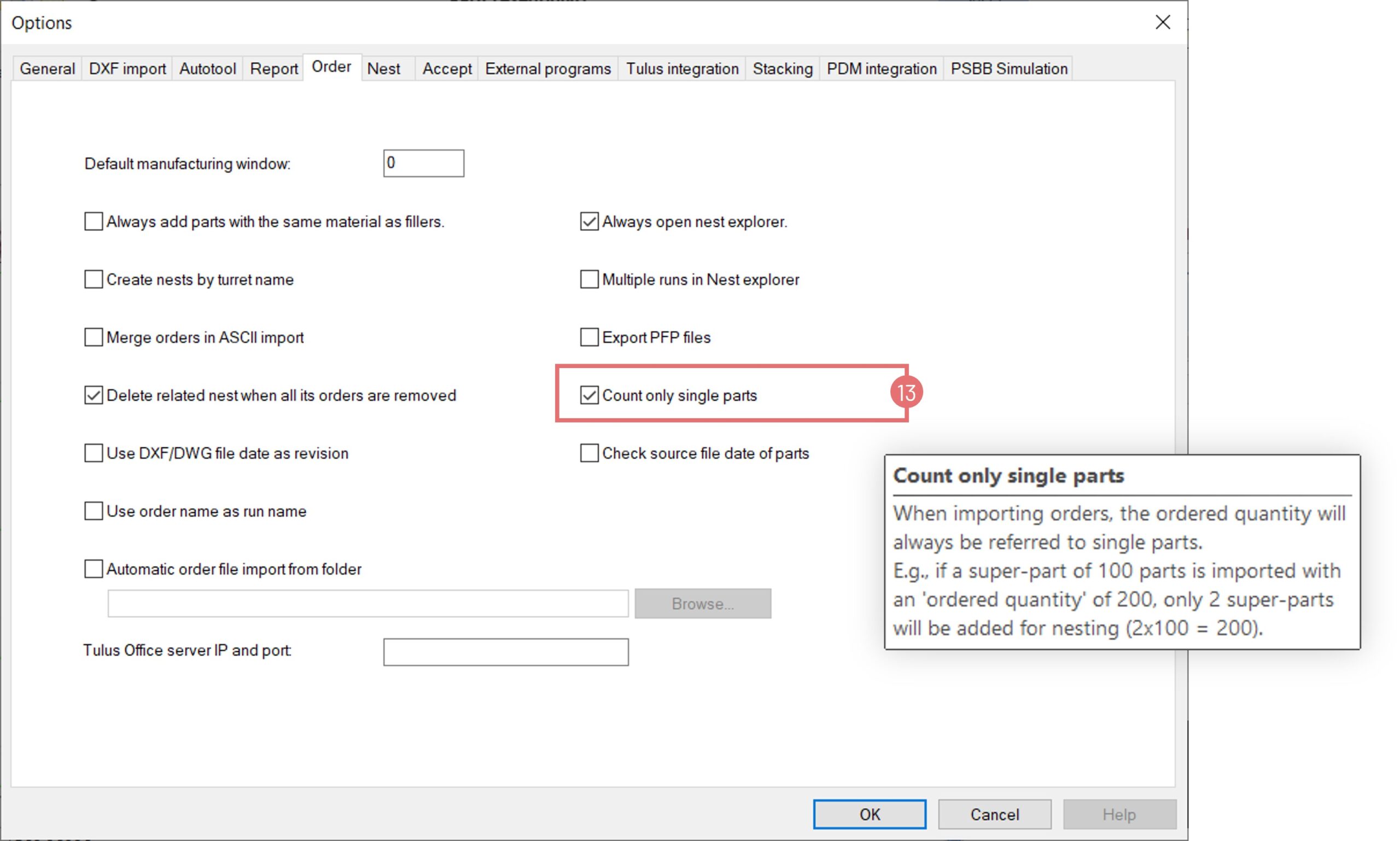
- Order Database Filters: New filters by part name and notes; bulk removal and export options.
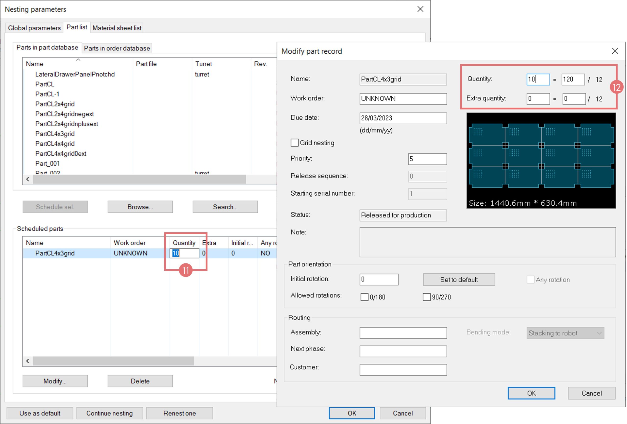
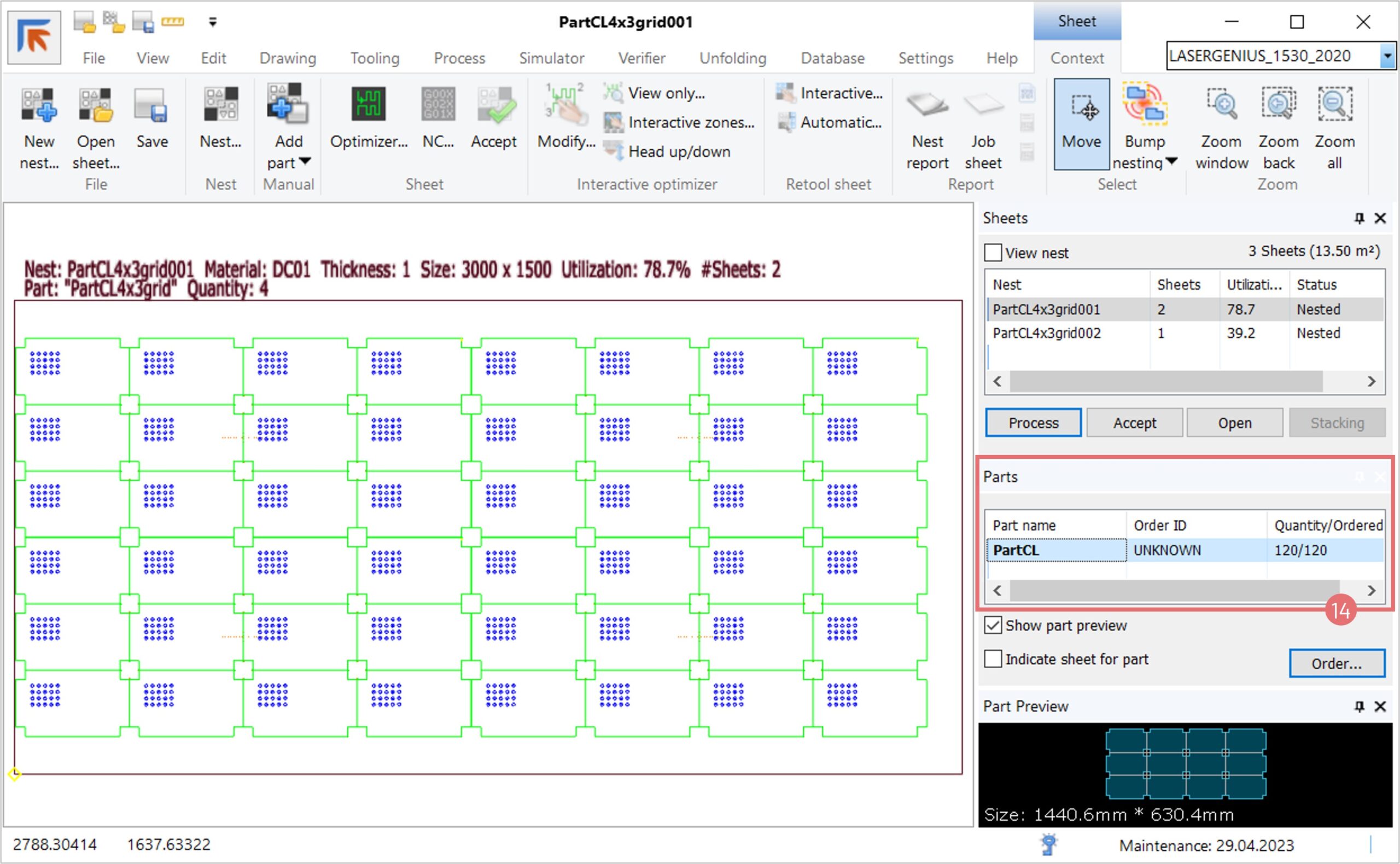
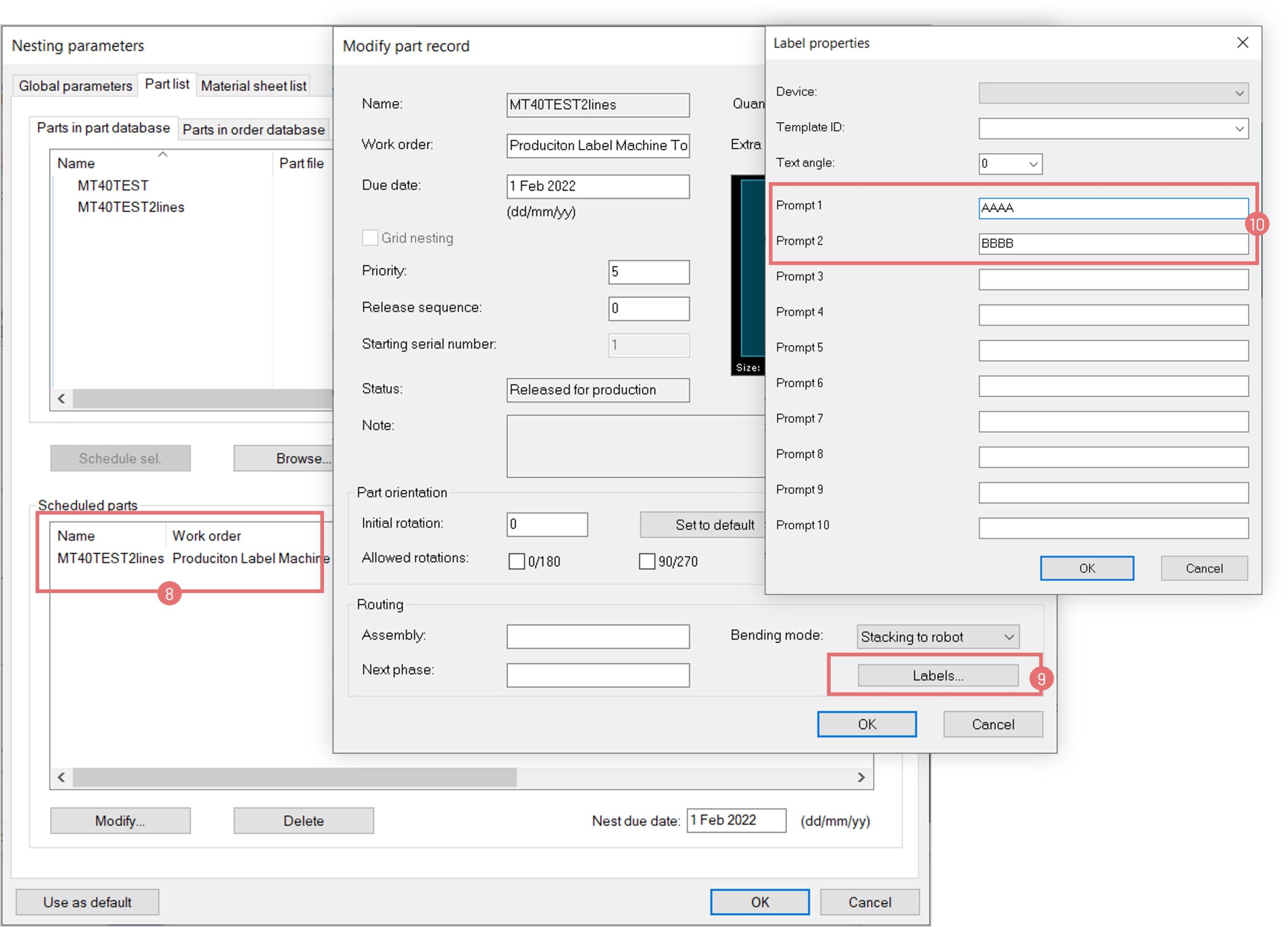
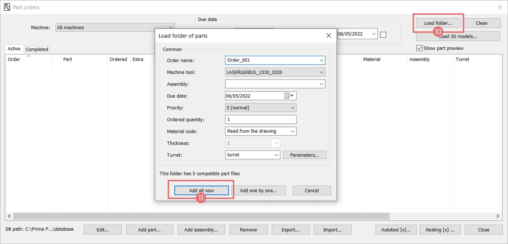
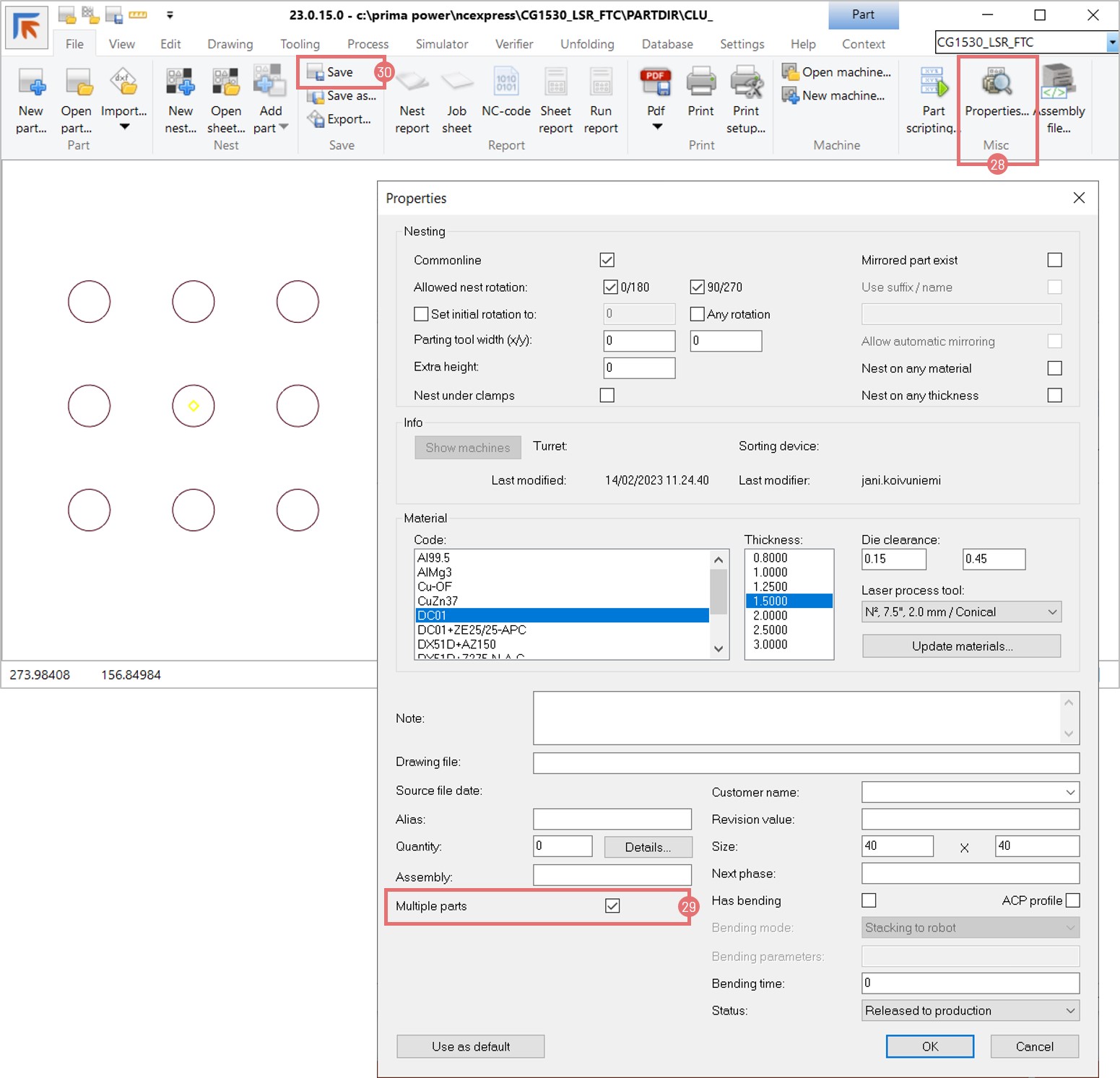
- Multi-Part Selection: Add multiple parts from the order database to nesting runs.
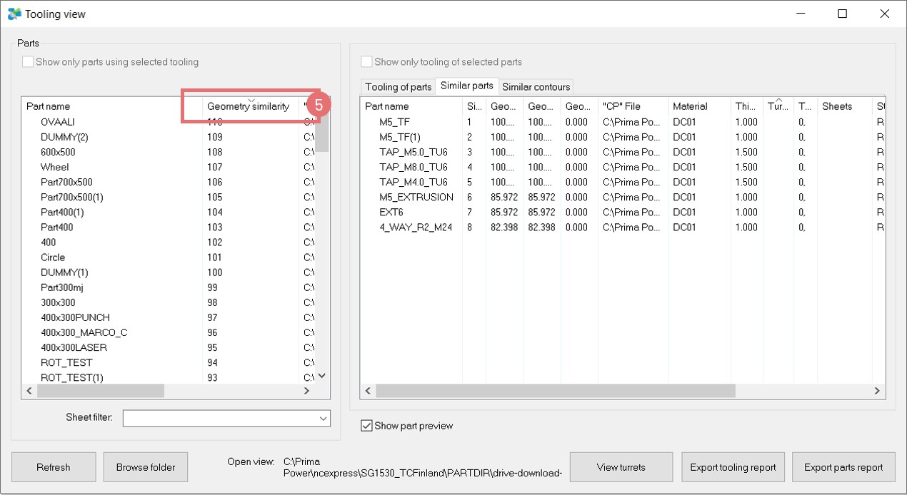
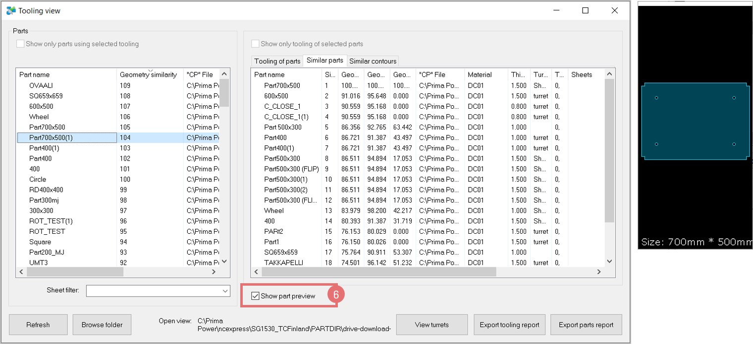
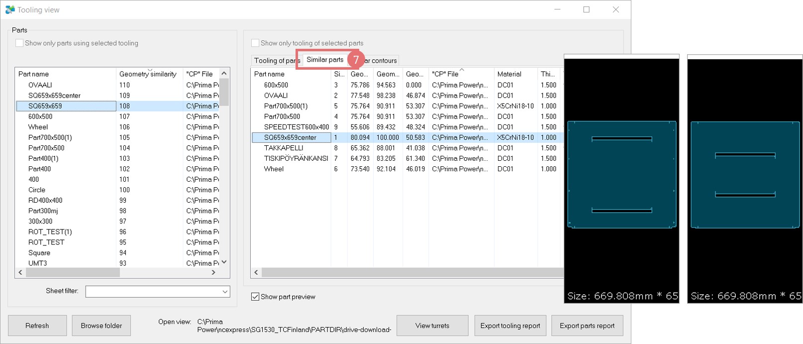
- Part & Nest Database Filters: Enhanced search by thickness, sheet size, and nesting name.
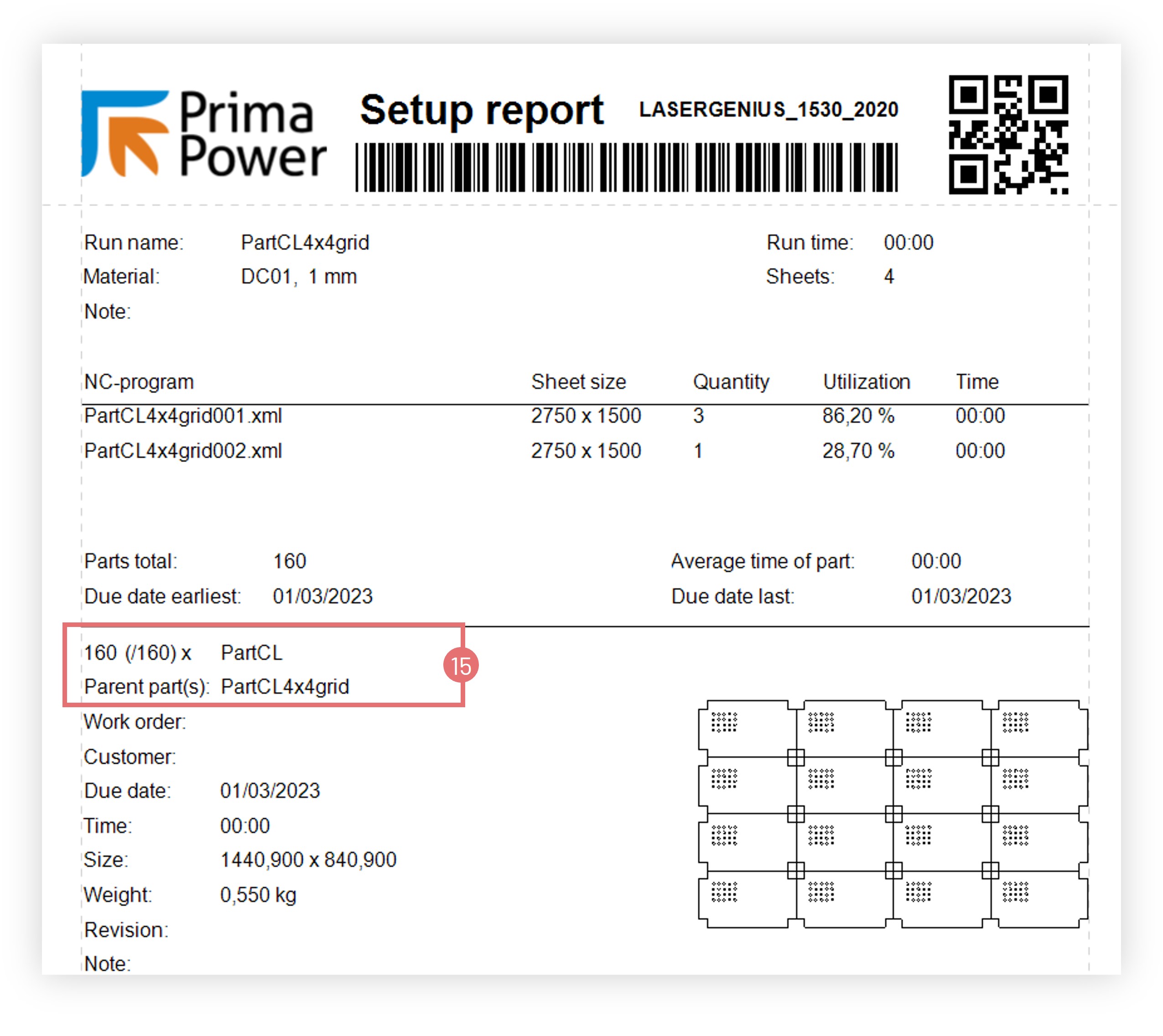
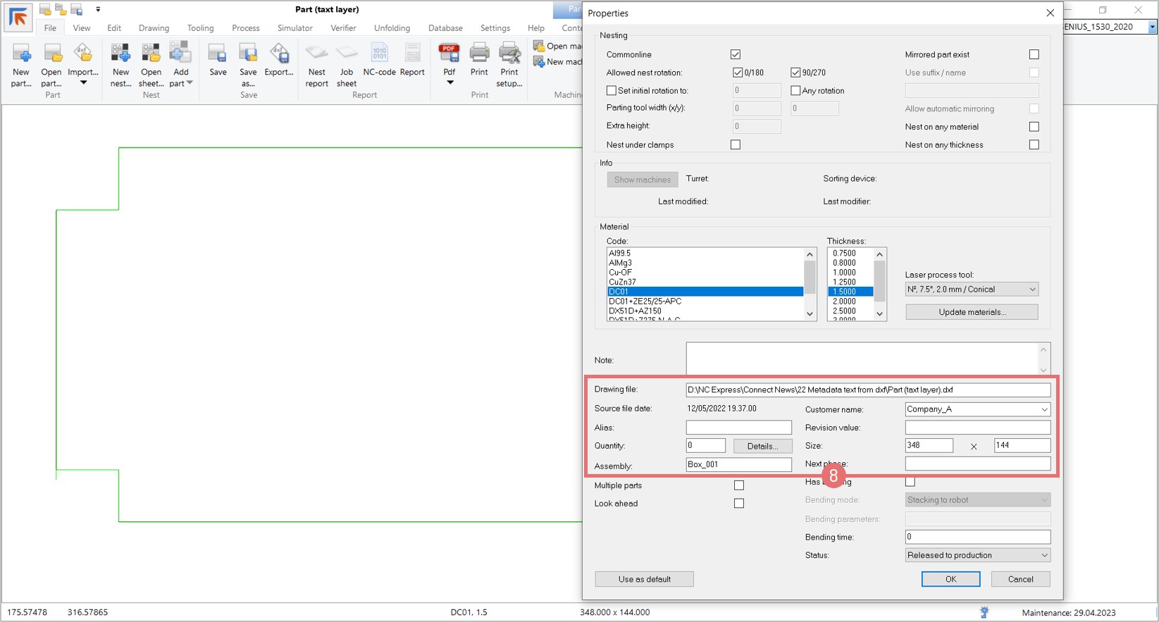
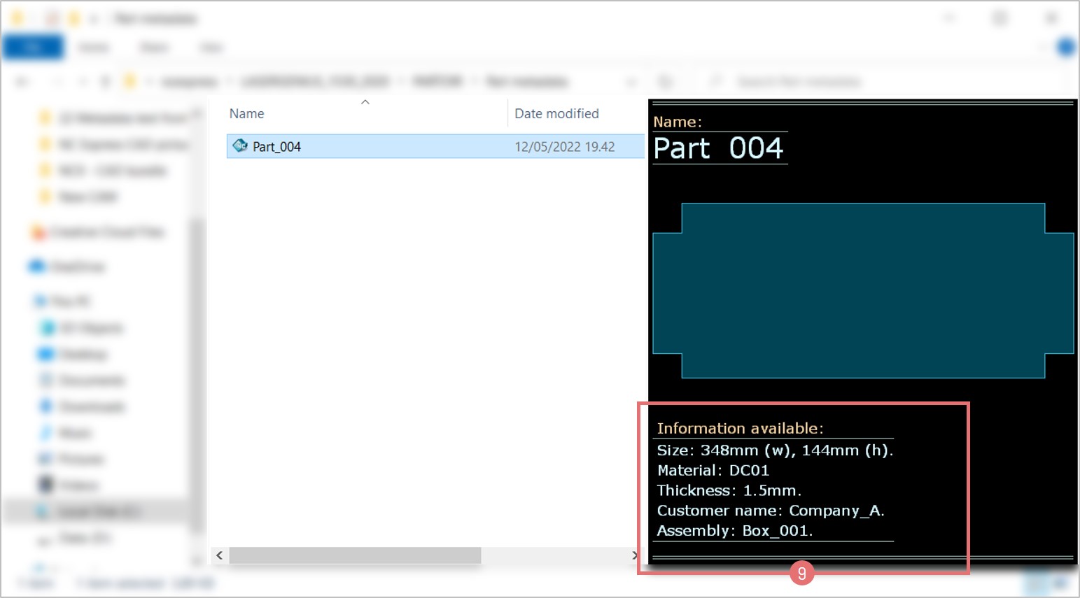
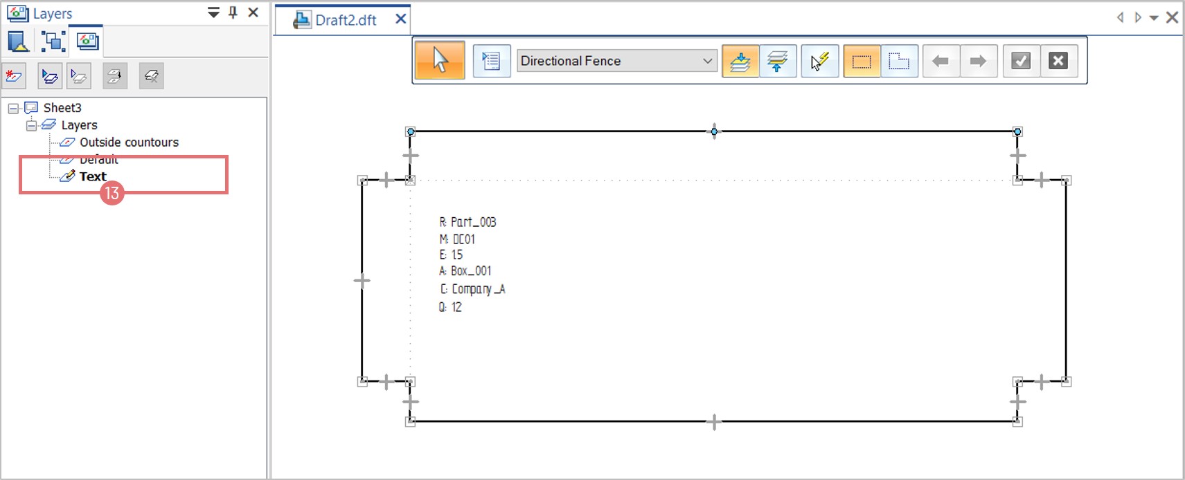
- Parts List & Database Info: Displays part revision and next phase directly in the interface.
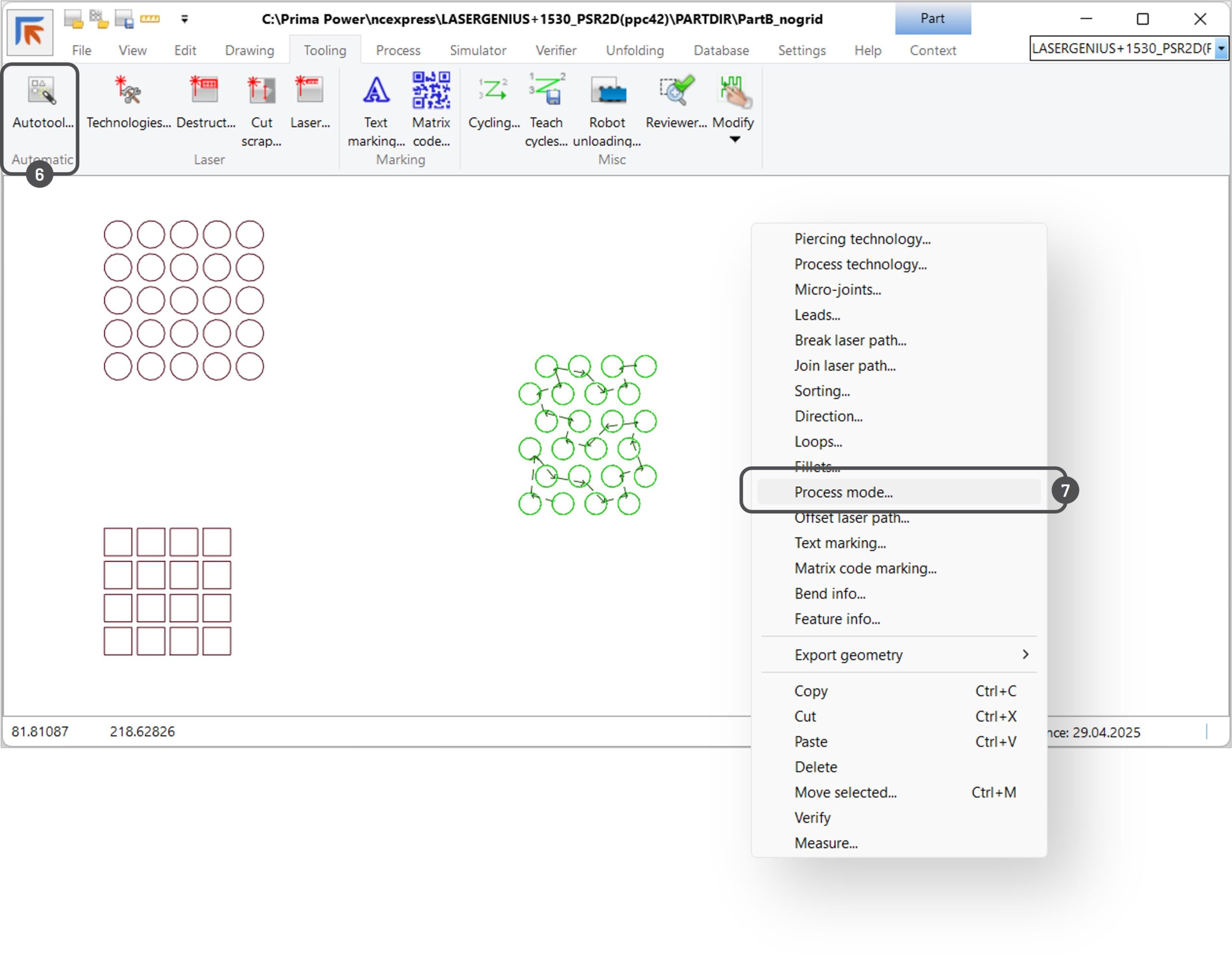
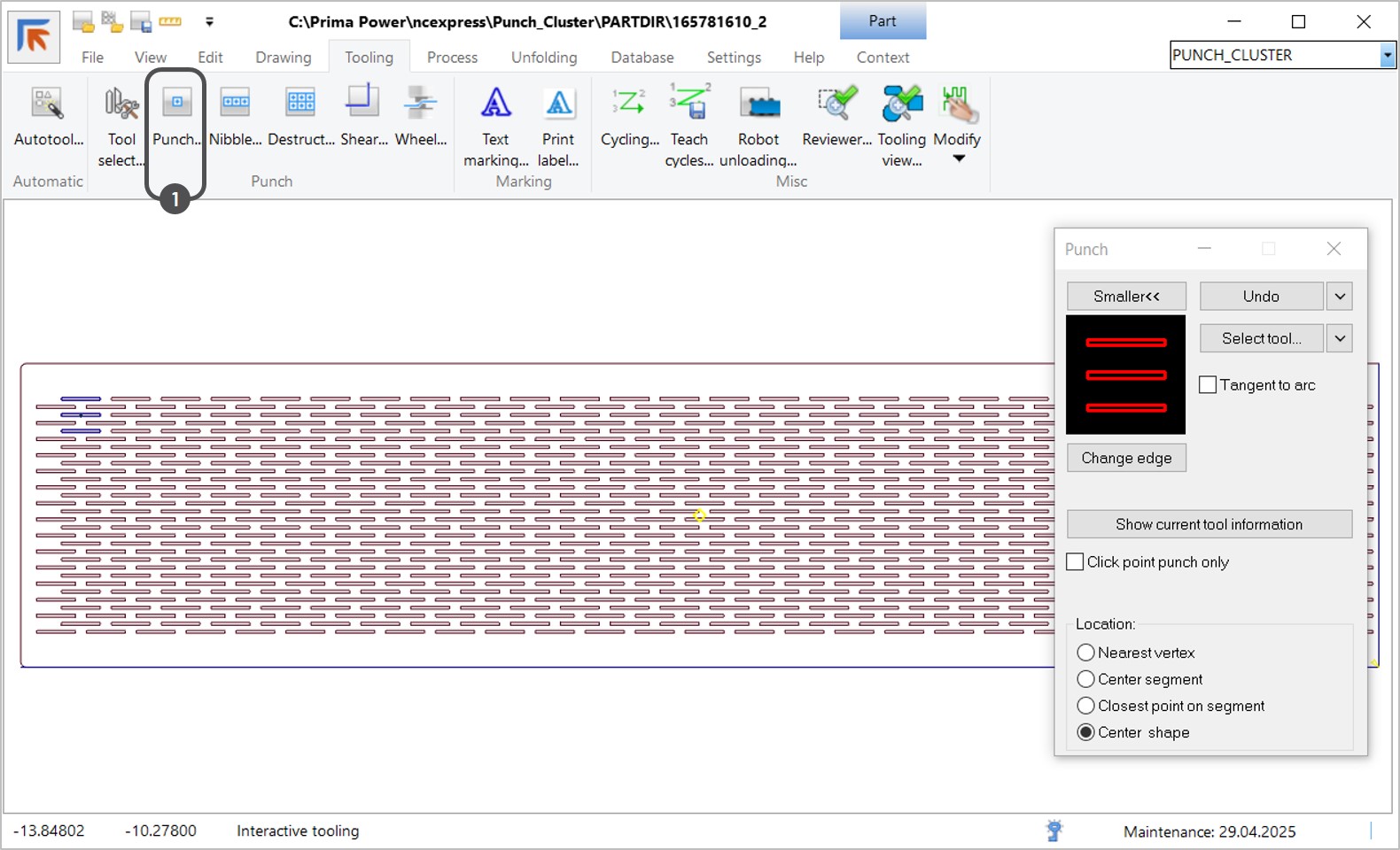
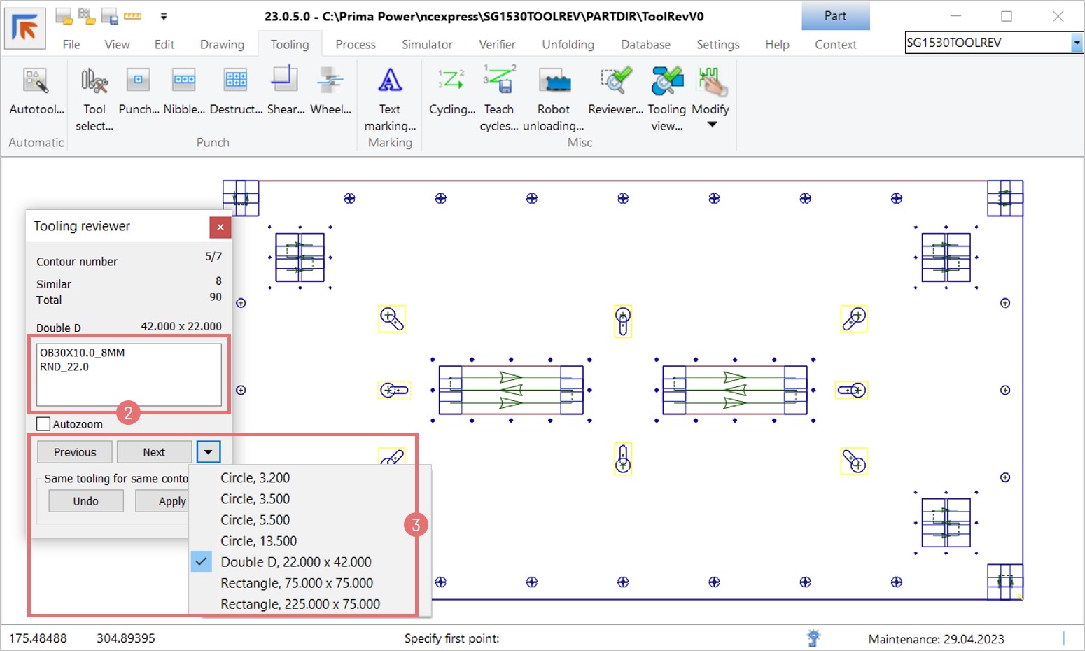
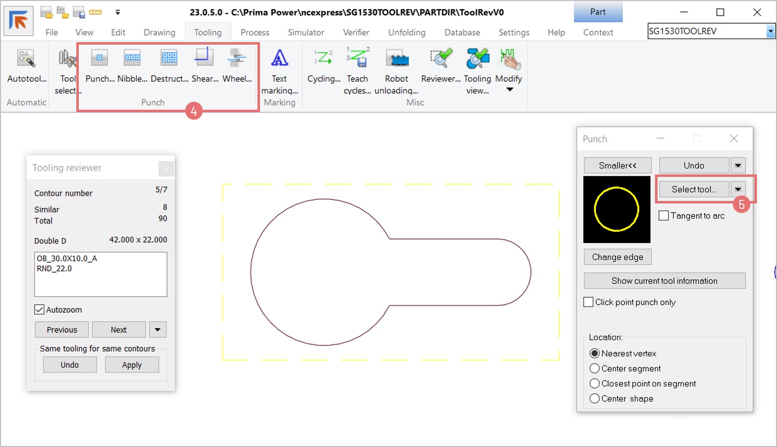
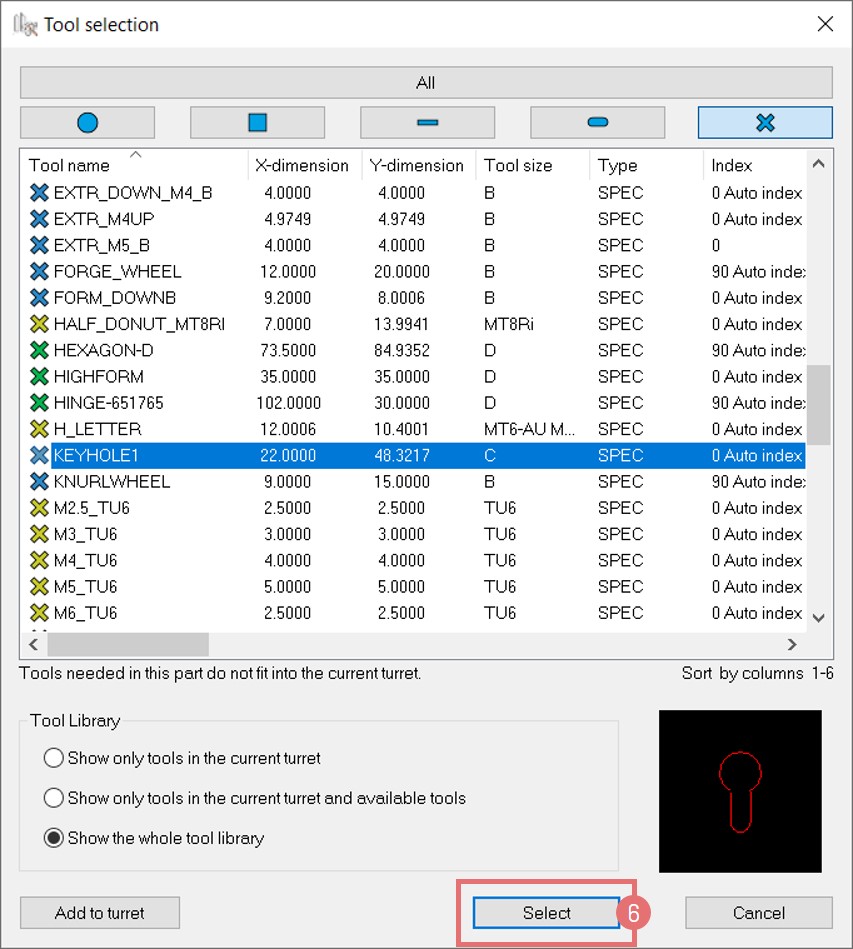
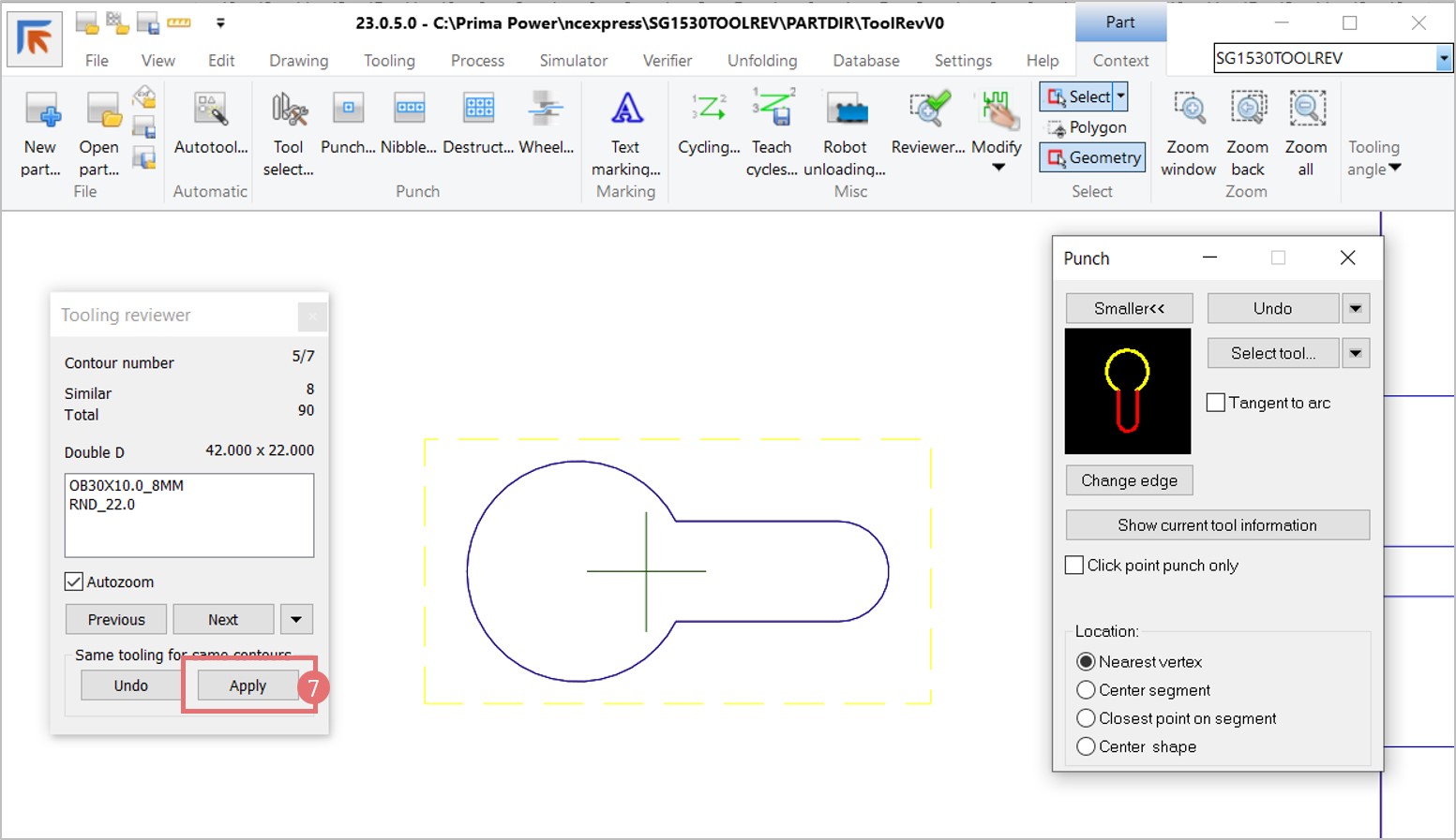
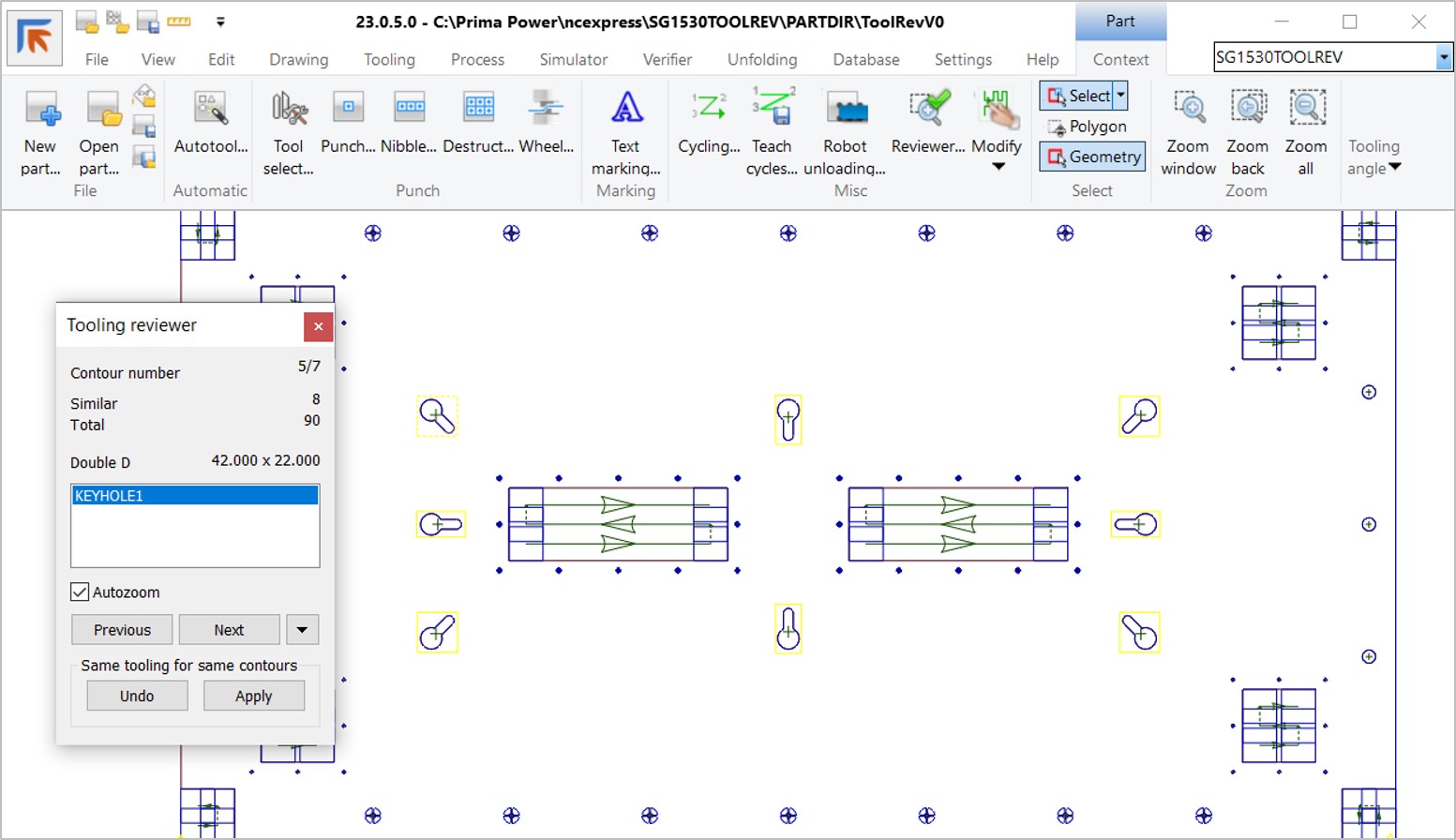
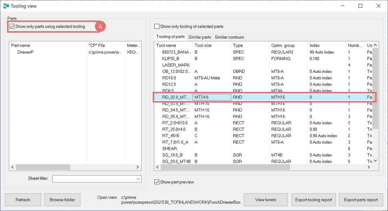
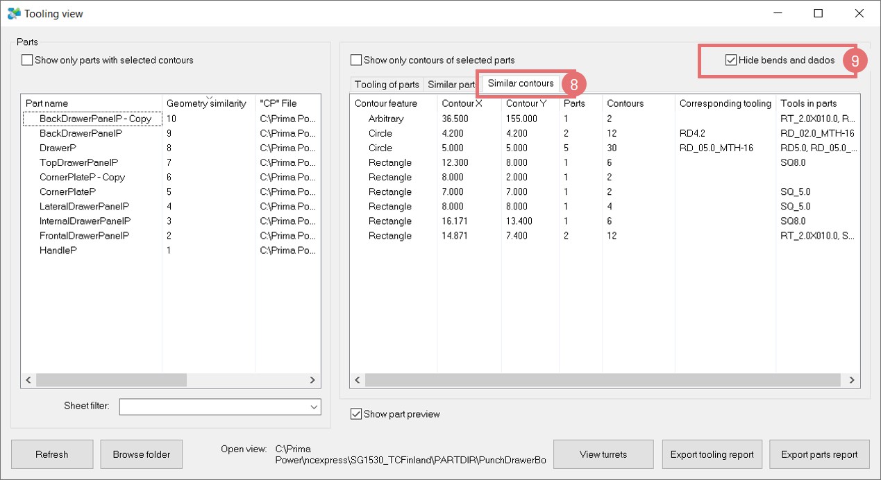
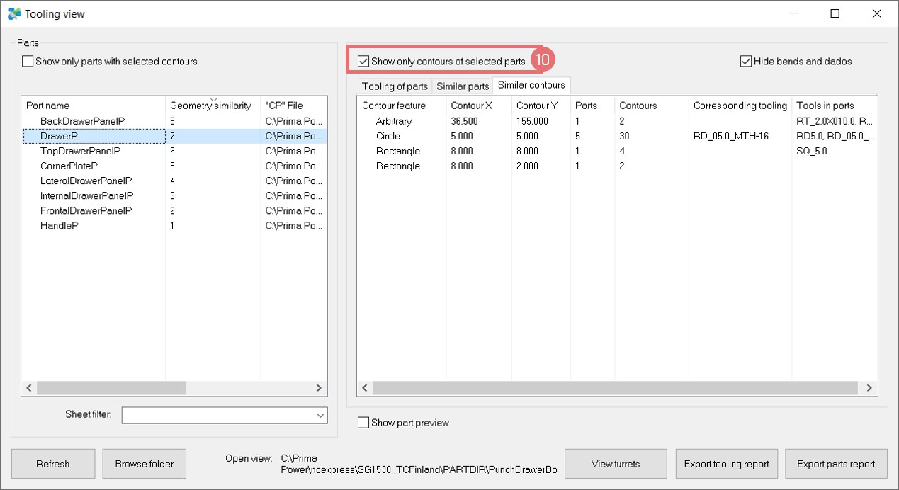
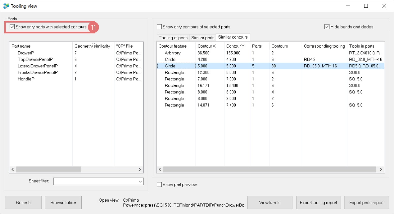
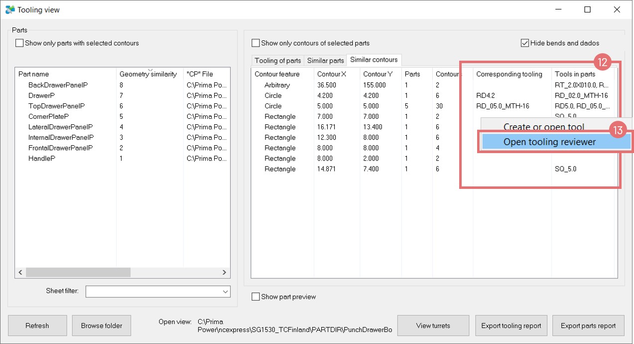
Tooling & Nesting Enhancements
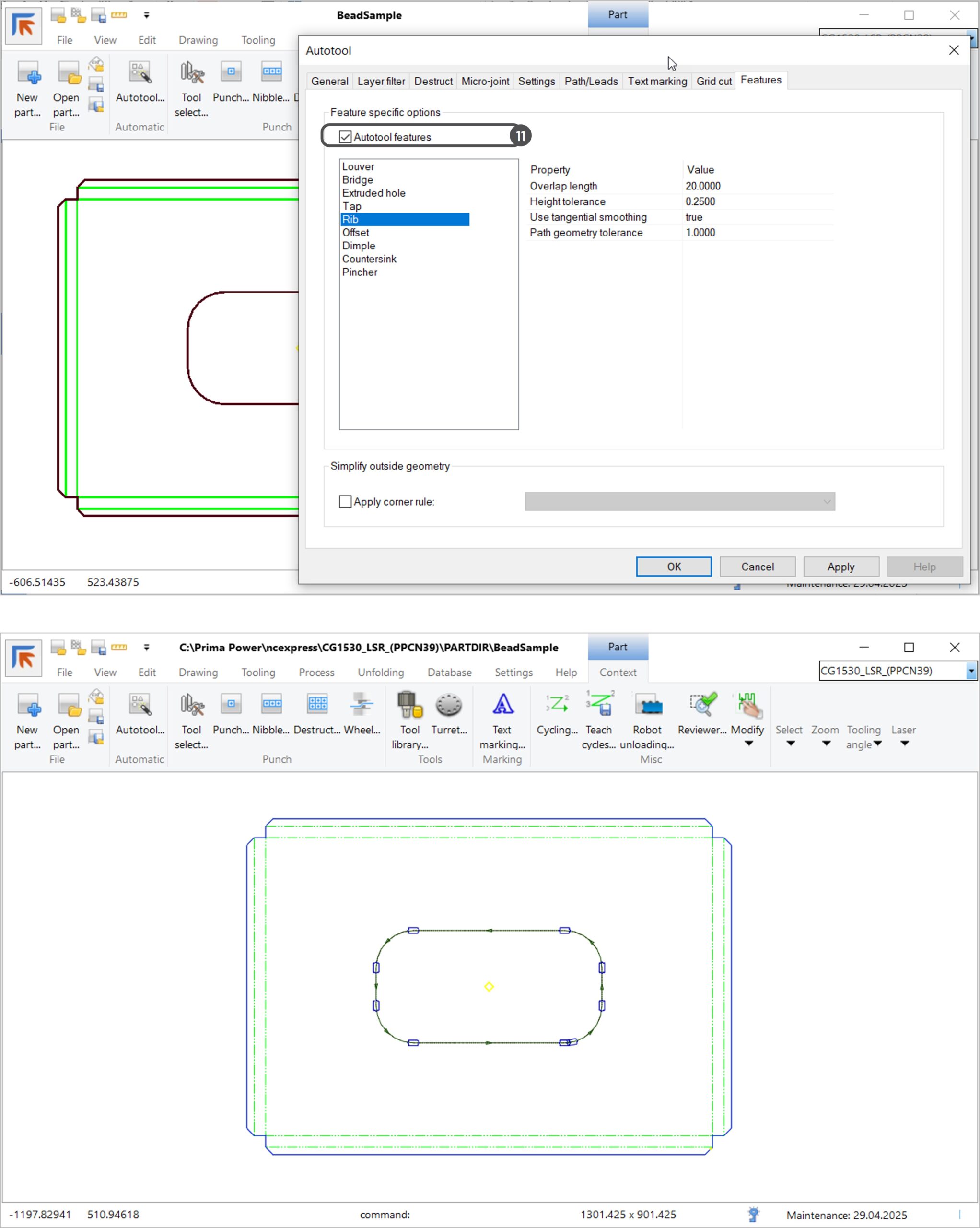
- Autotool Warnings: Alerts for geometry violations and untooled segments.
- Arrowhead Indicators: Visual cues for small slugs and untooled areas.
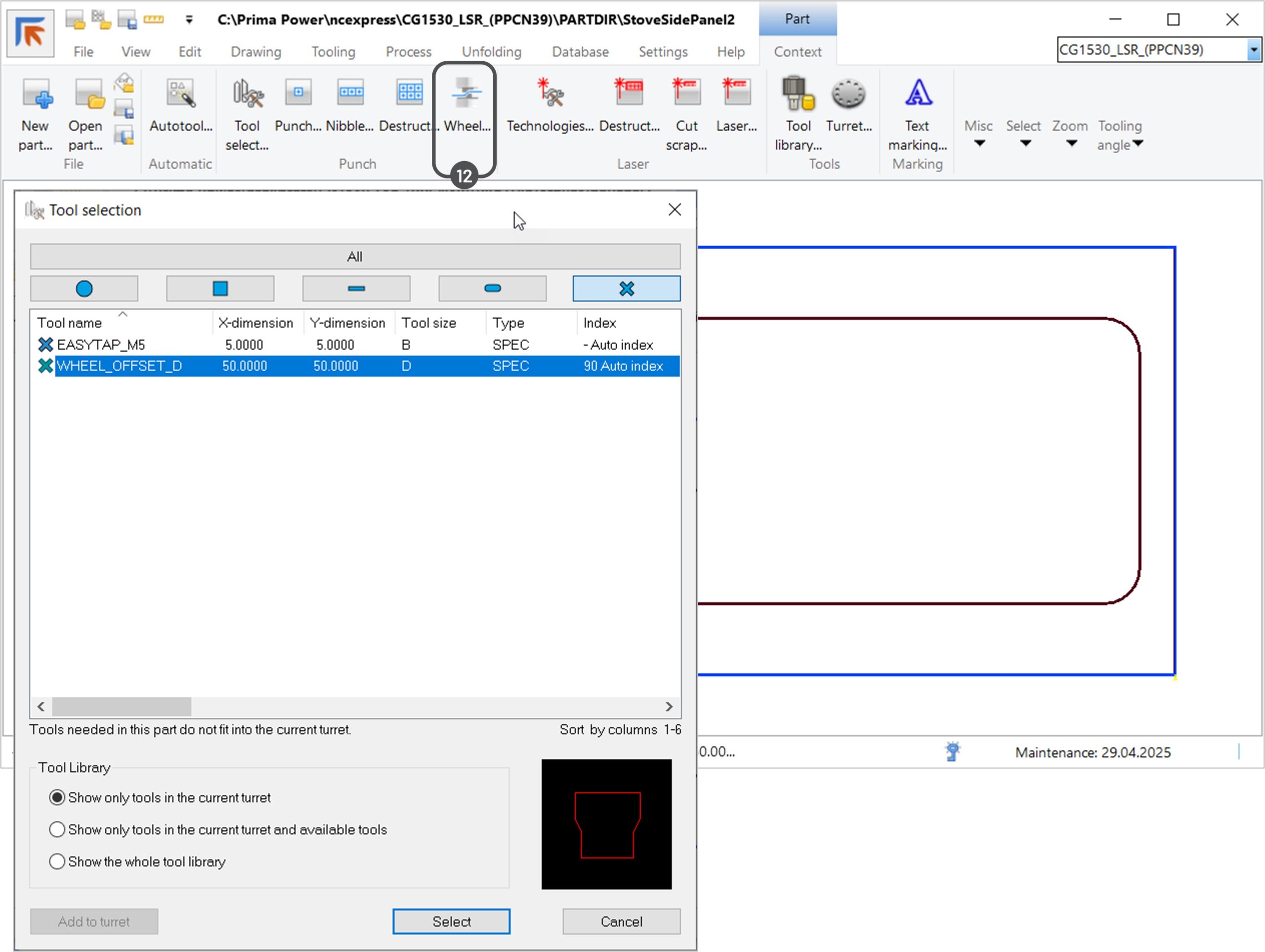
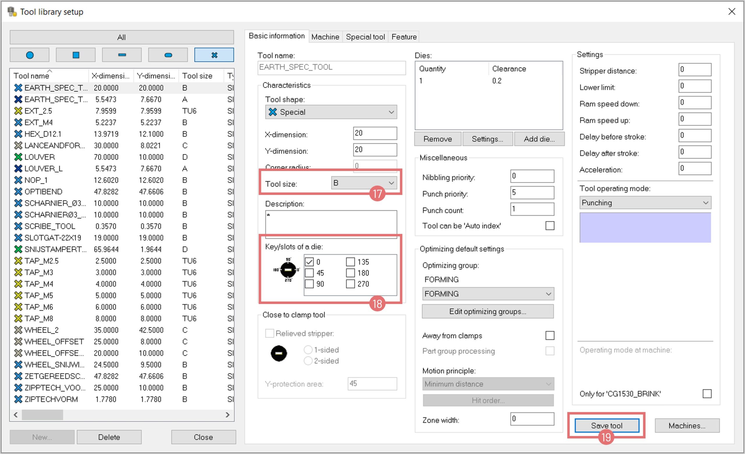
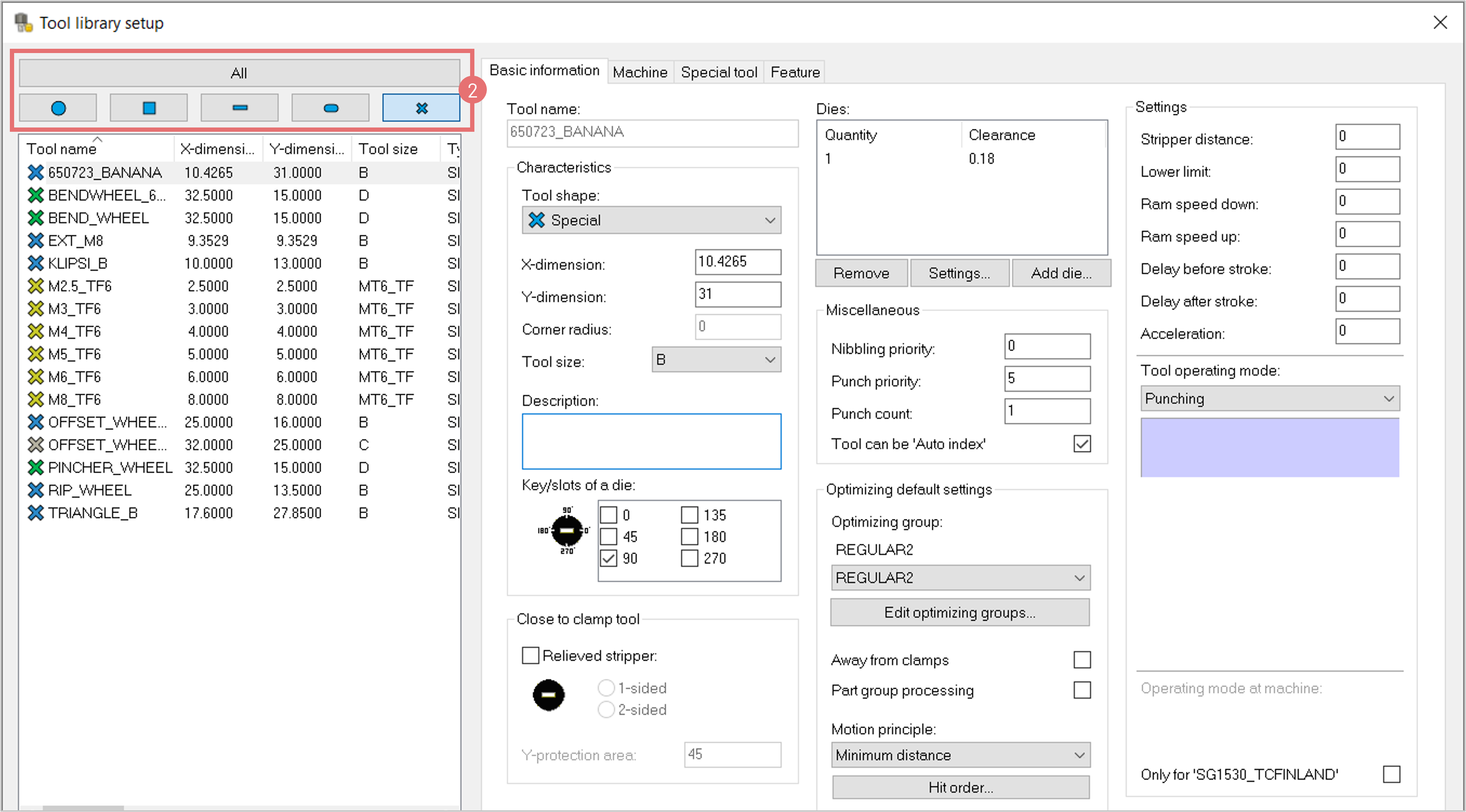
- Default Tool Size Check: Automatically selects appropriate station size based on tool dimensions.
- Panel Bender Programming: Improved programming capabilities for EBe and BCe machines.
- Unfolding Enhancements: Support for the latest 3D formats and versions, including Autodesk Inventor, SolidWorks, Solid Edge, Siemens JT, Siemens NX, PTC Creo, Catia, IGES, STEP, Spatial ACIS, and Parasolid.
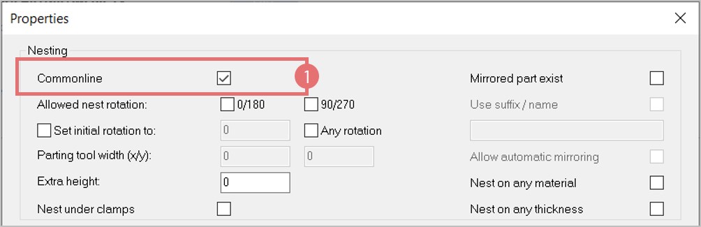
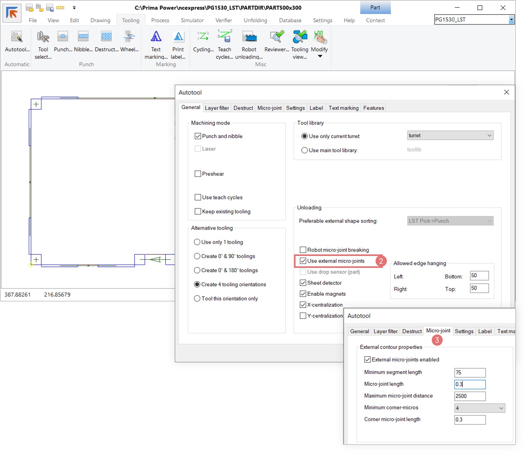
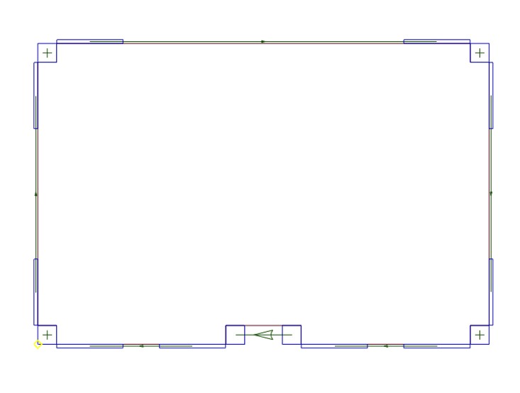
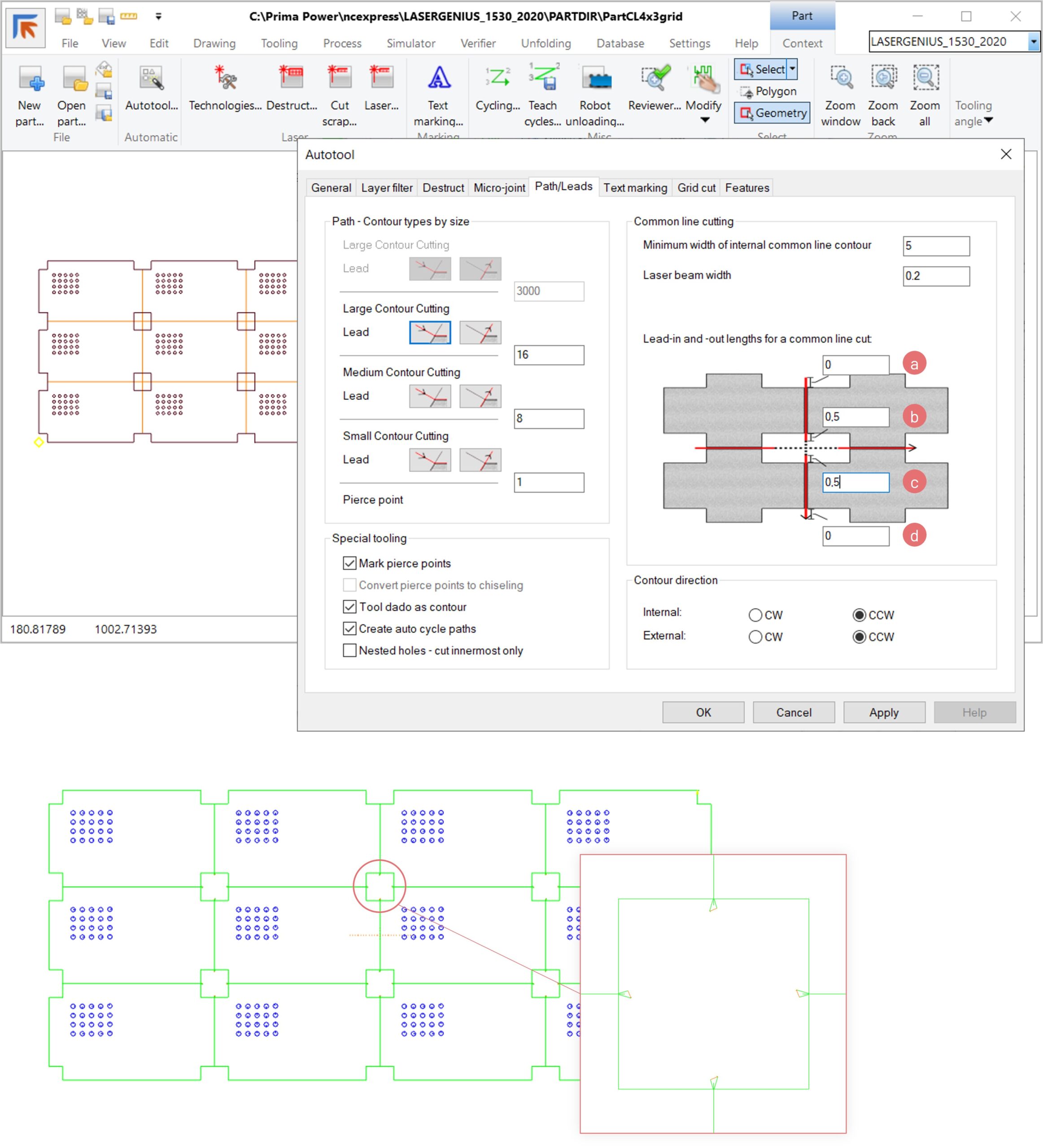
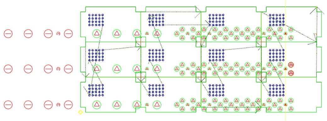
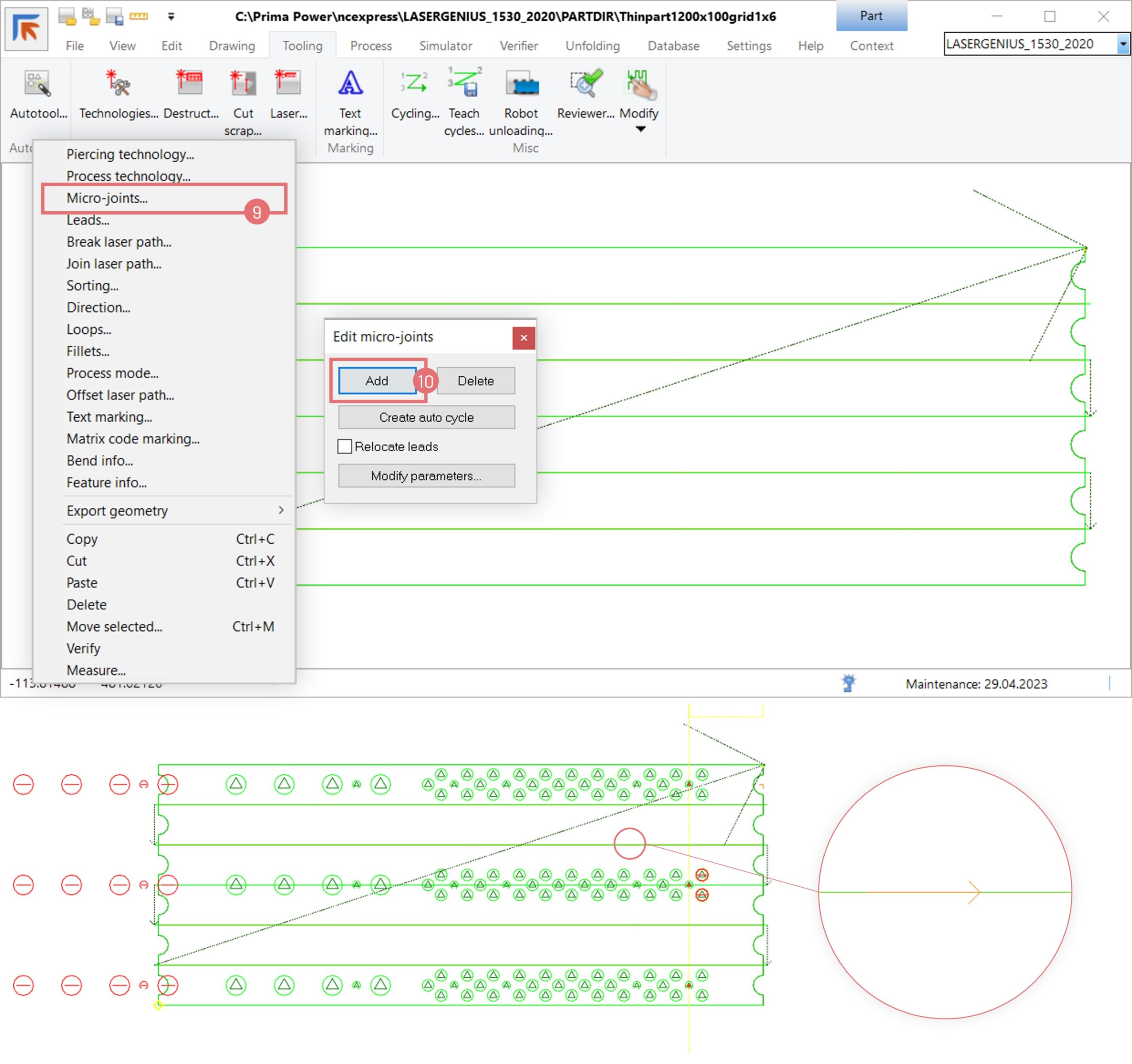
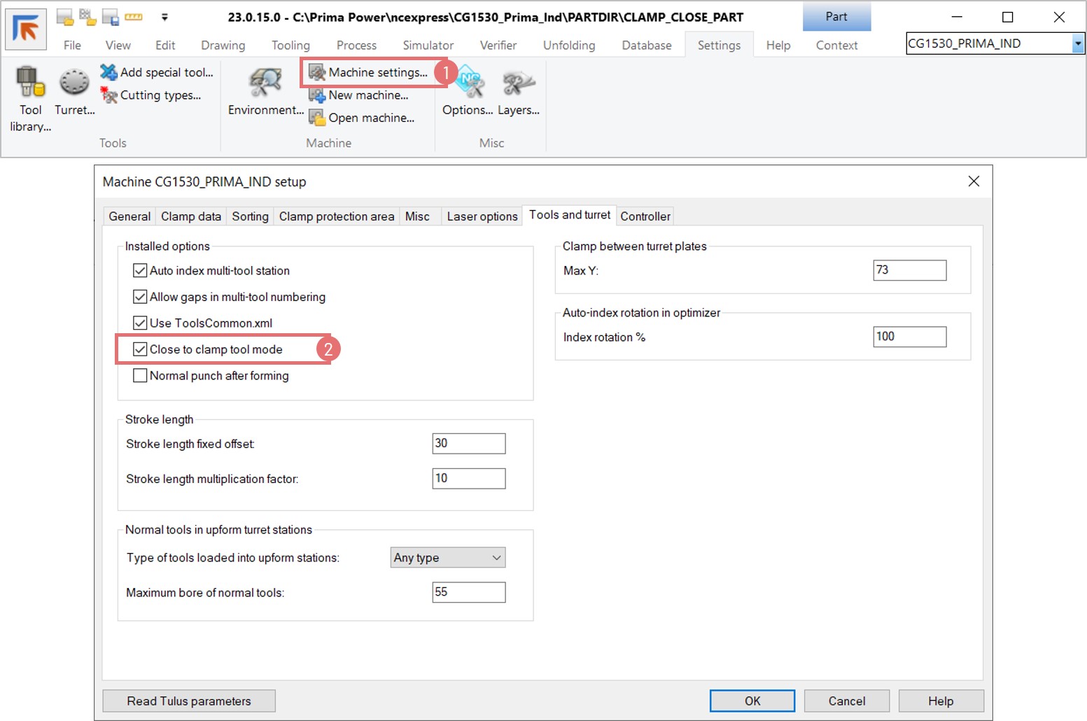
- Micro-Jointed Area for Manipulator Clamping: New feature to set internal contours for micro-jointing, enhancing part clamping during bending.
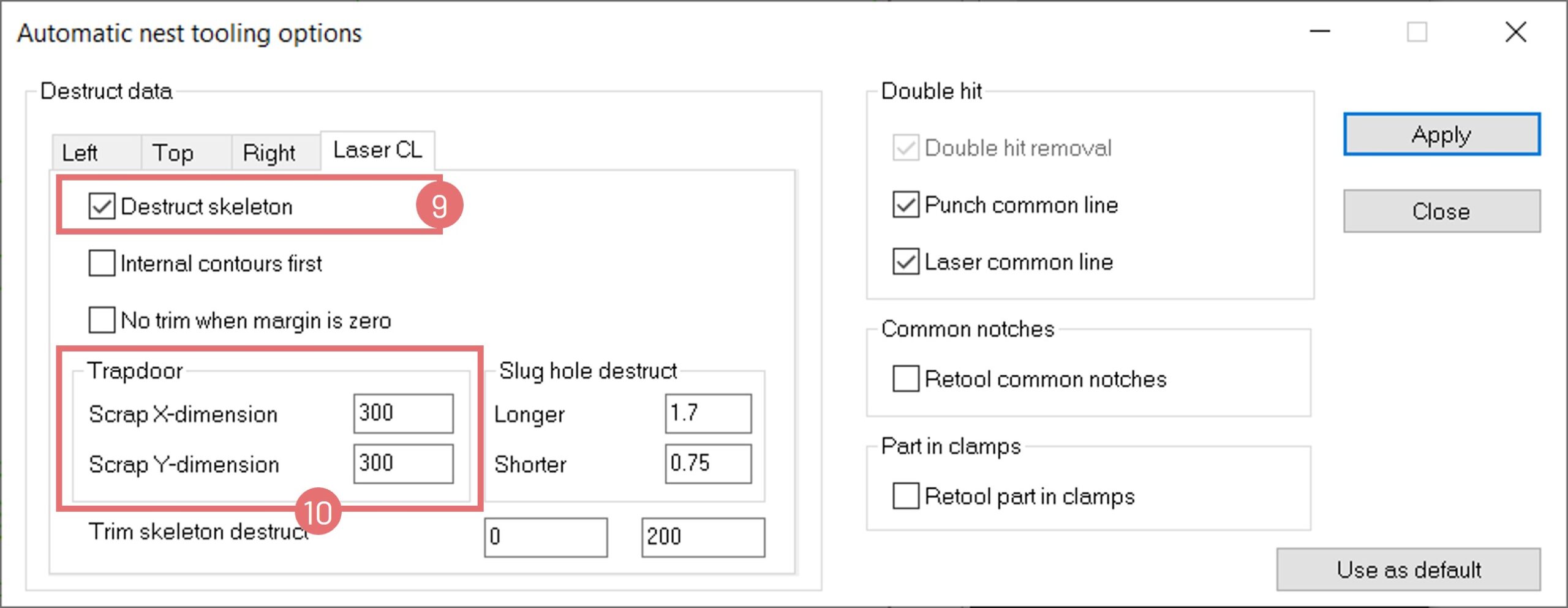
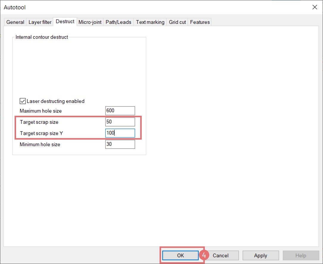
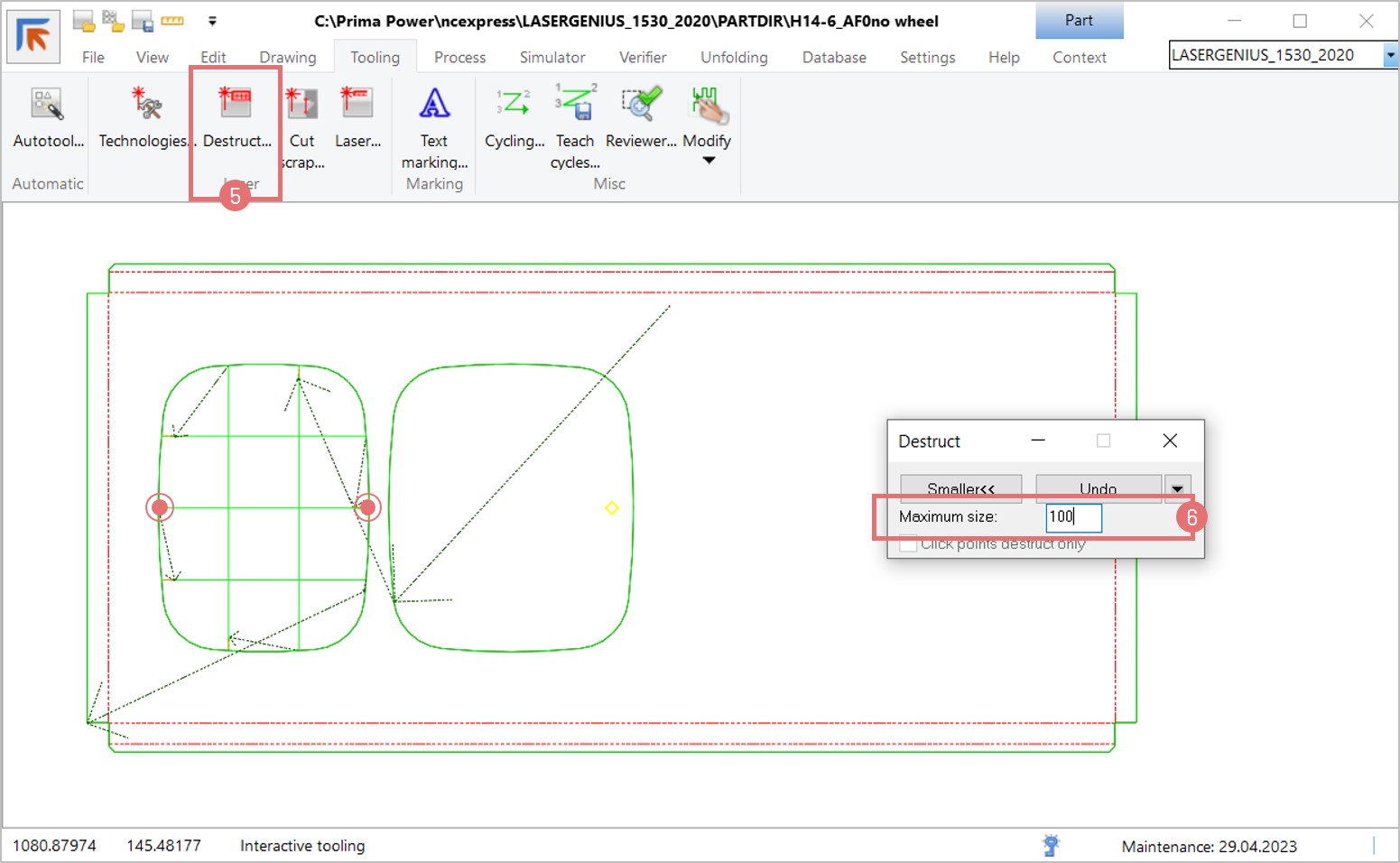
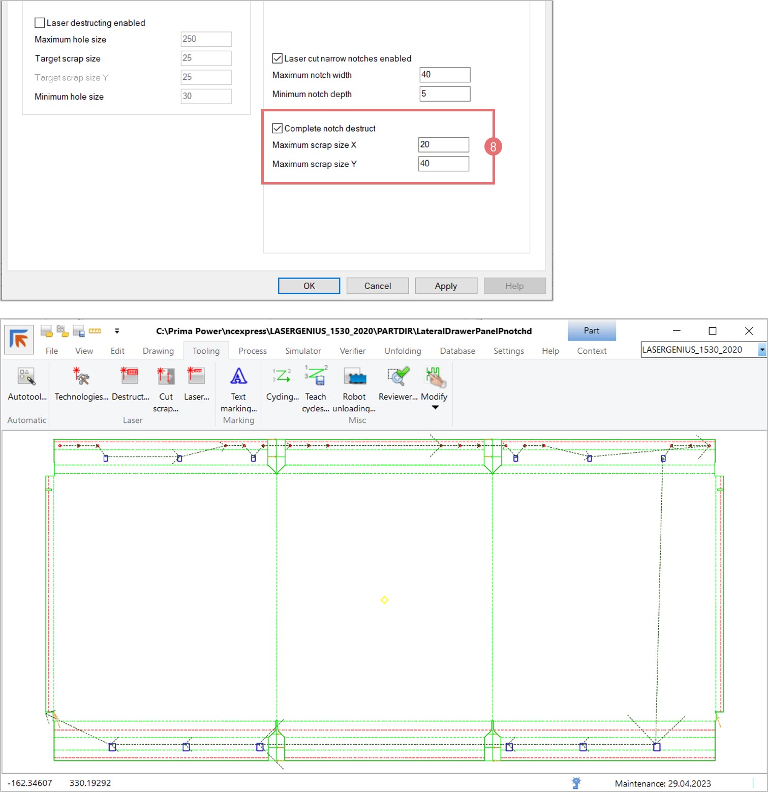
- Laser Machine Enhancements: New scrap settings for every edge of the sheet, laser surface processing with selected line types/colors, and support for Platino Linear and Sinumerik One 3D Laser.
- Punch-Shear Machines: Support for bend relief machining with milling heads and setting cassette types in CAM.
- Laser-Punch Machines: Enhanced laser surface processing, external part marking device support, and laser crop lines in both X and Y directions.
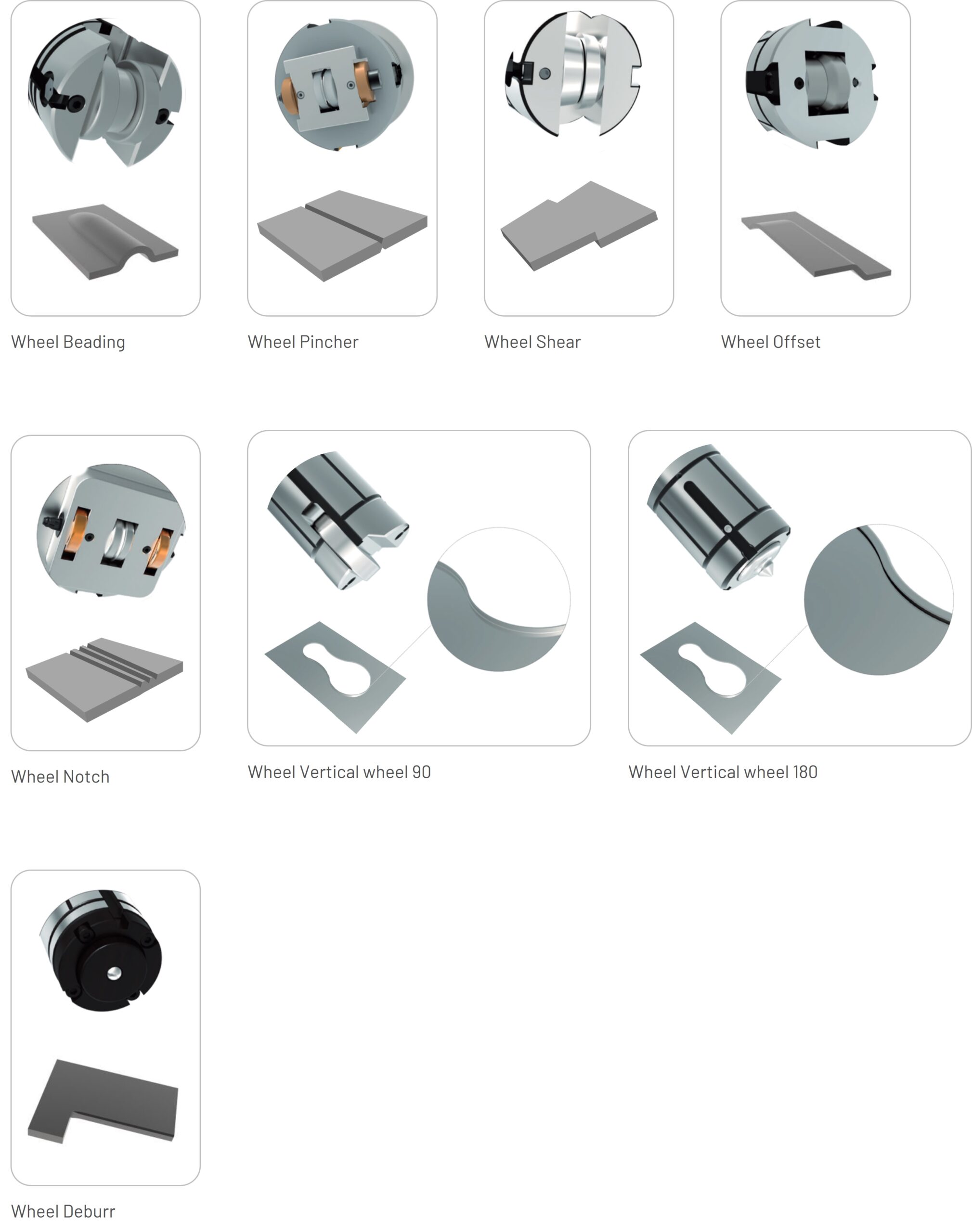
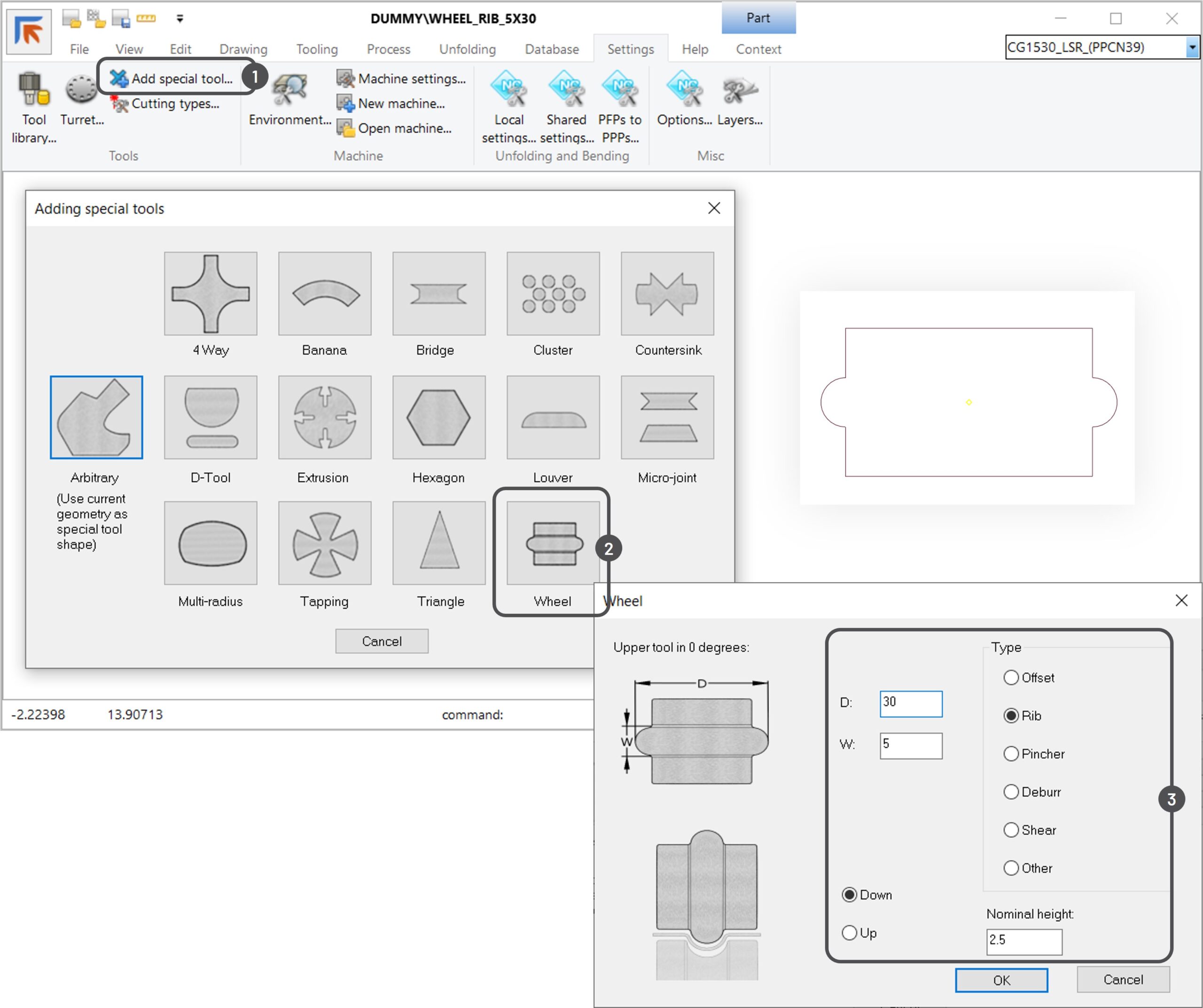
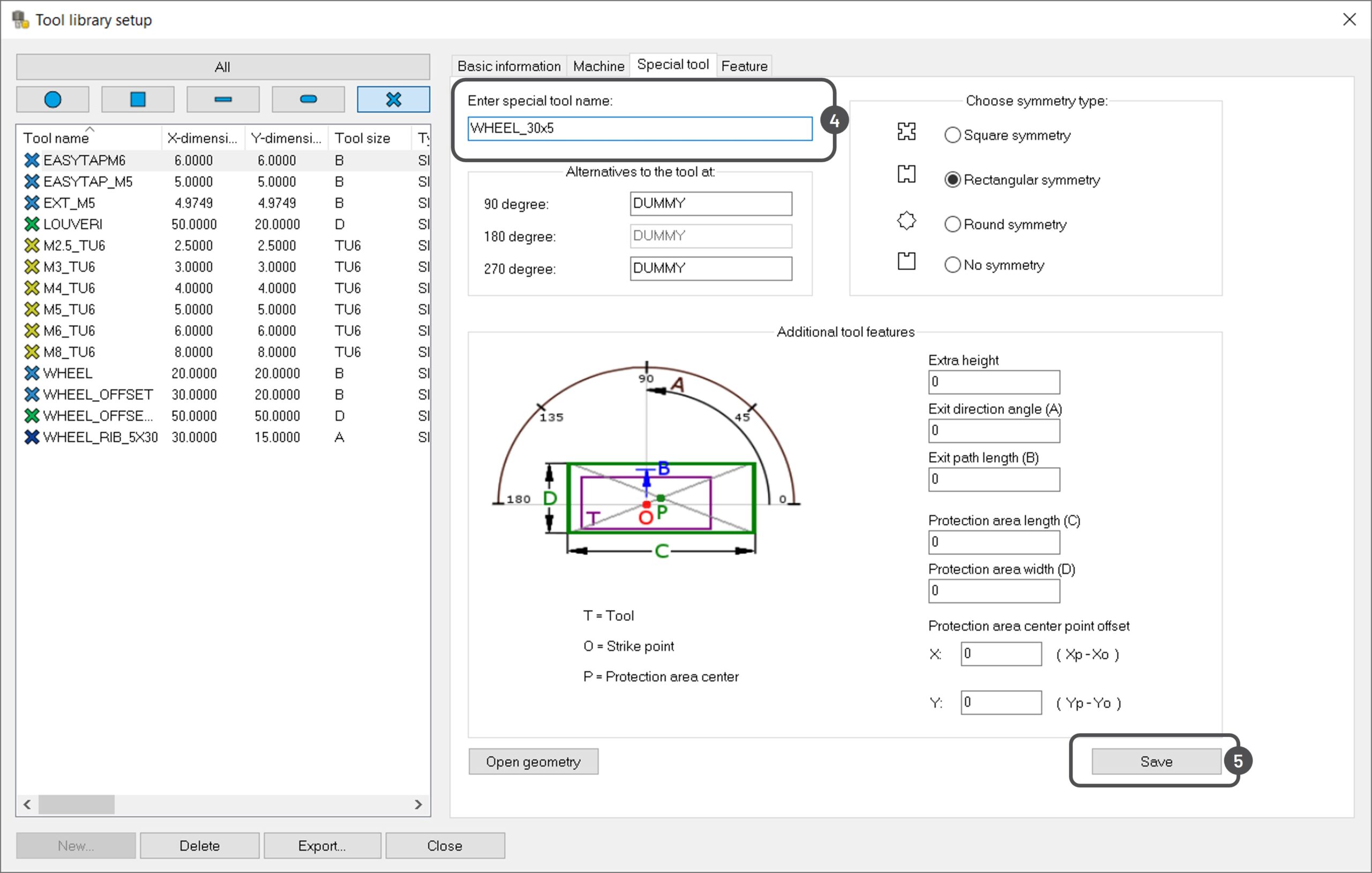
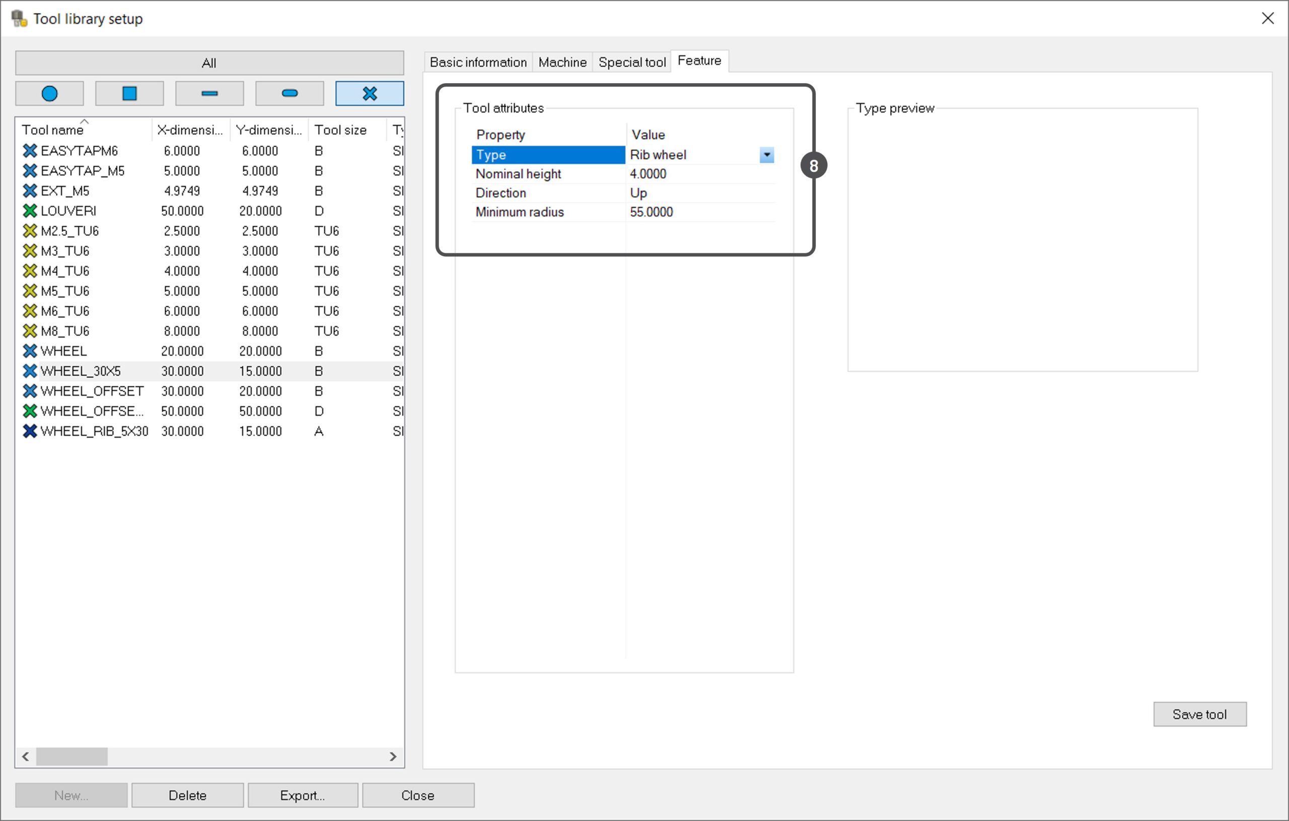
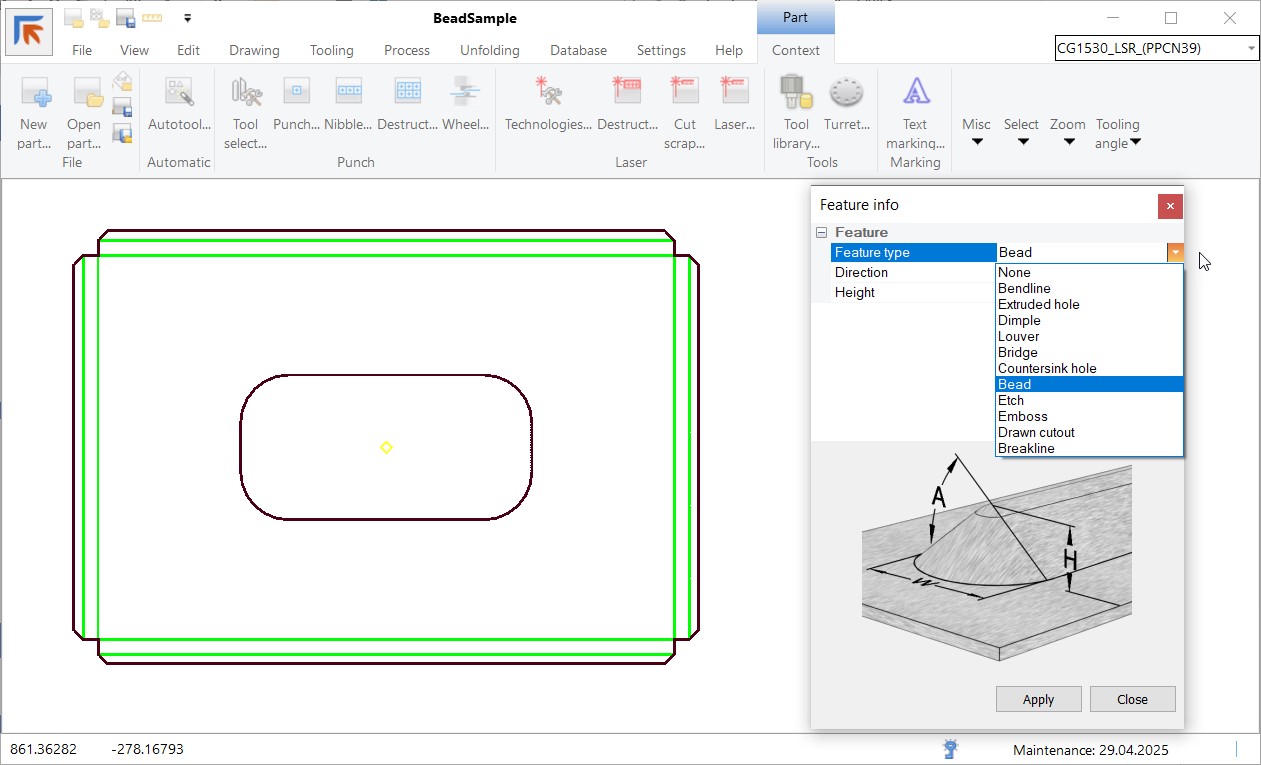
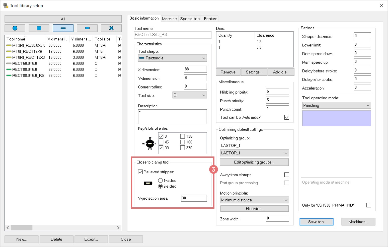
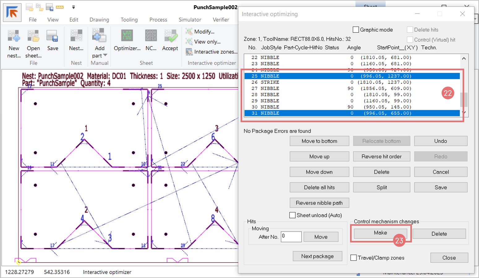
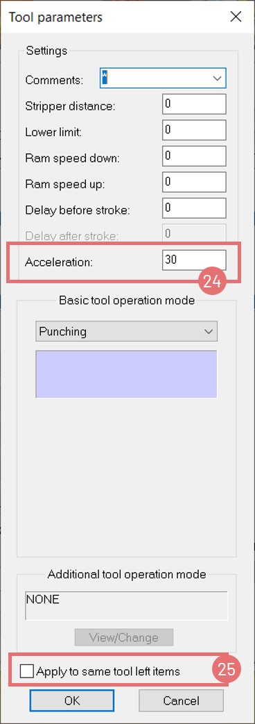
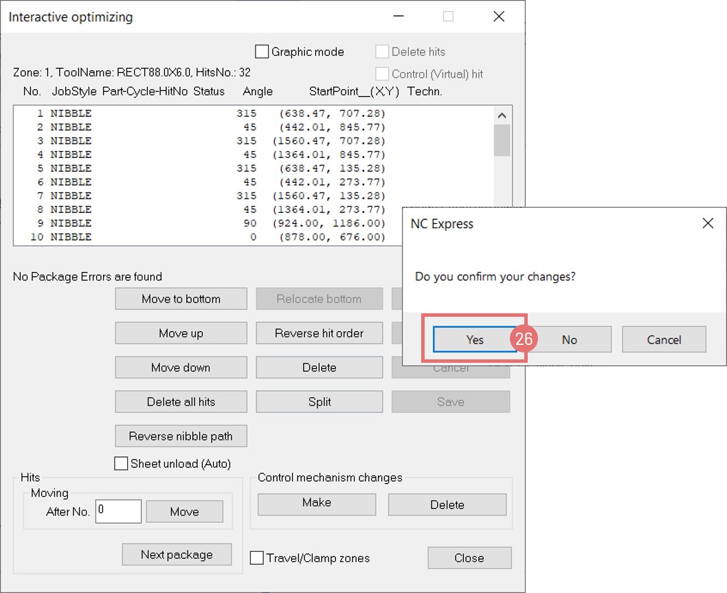
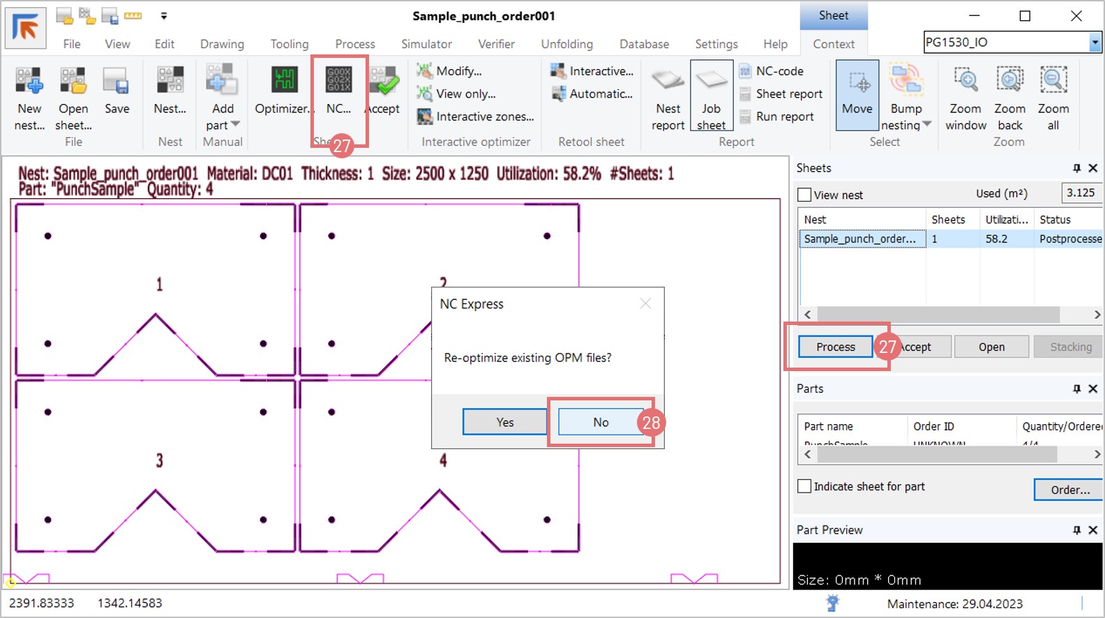
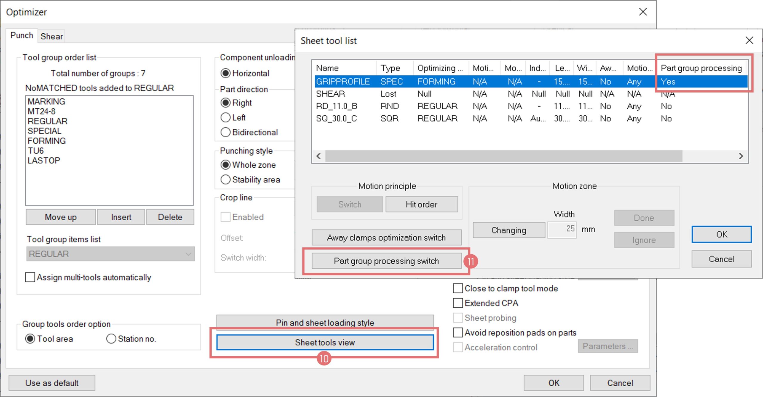
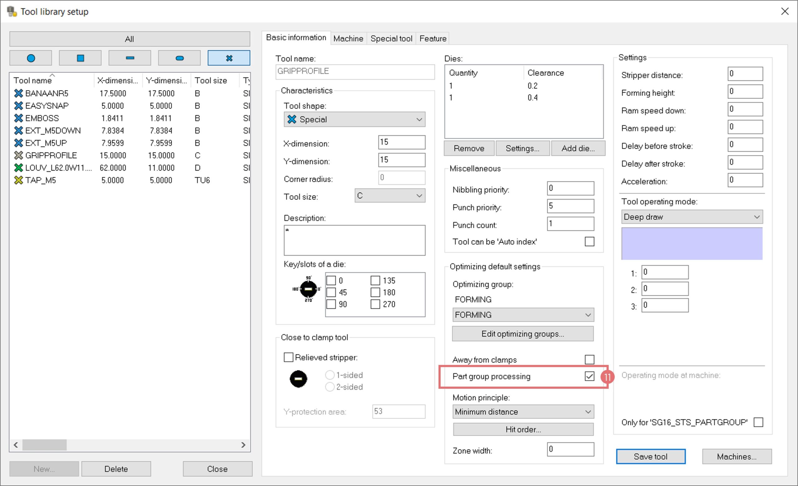
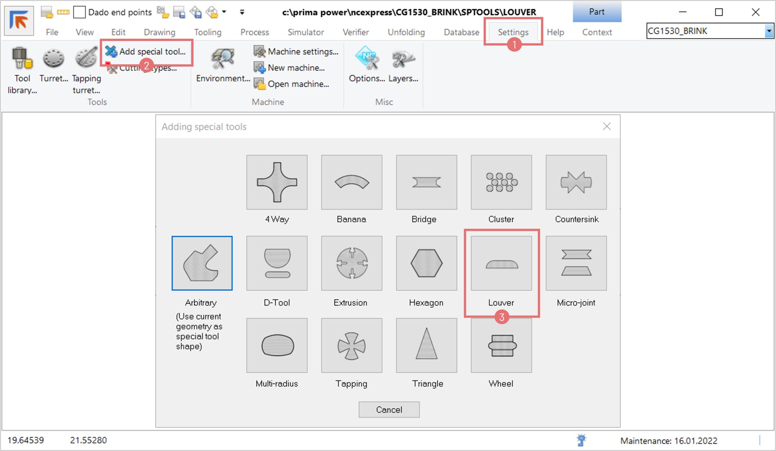
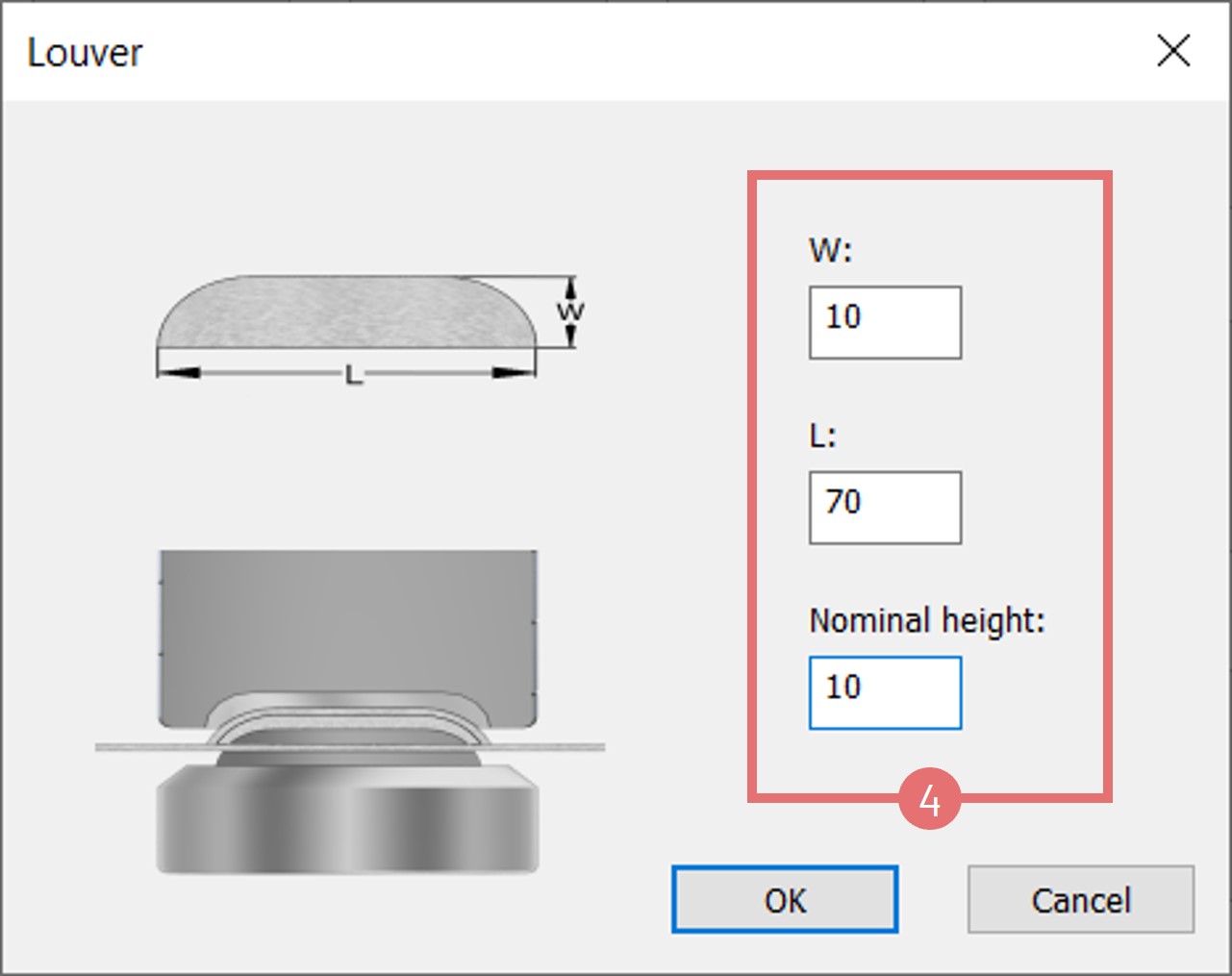
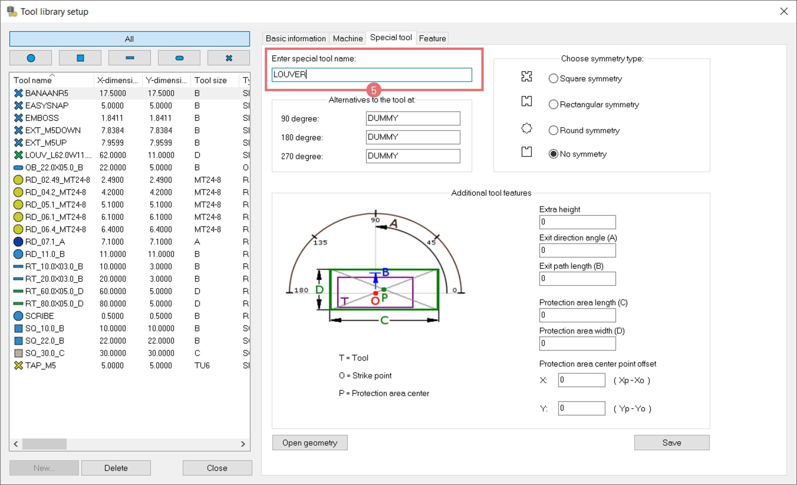
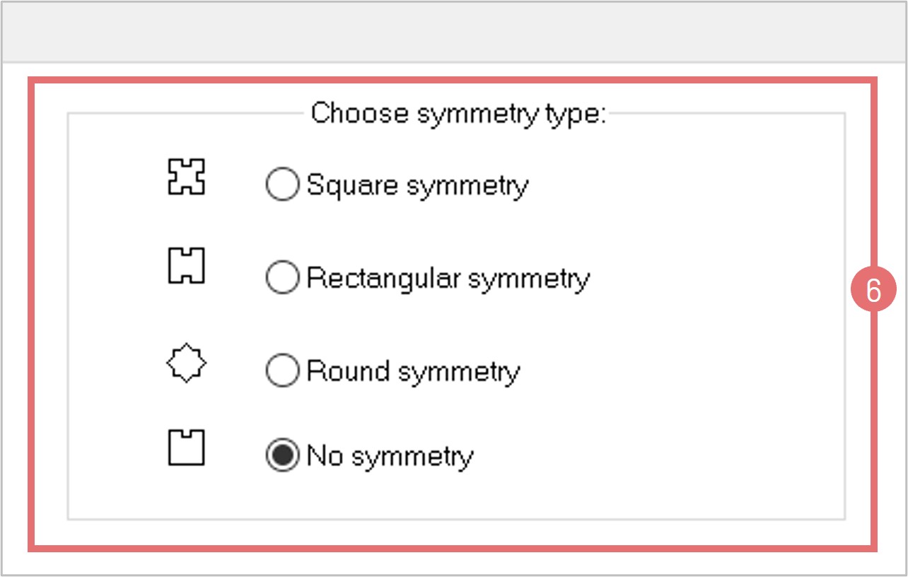
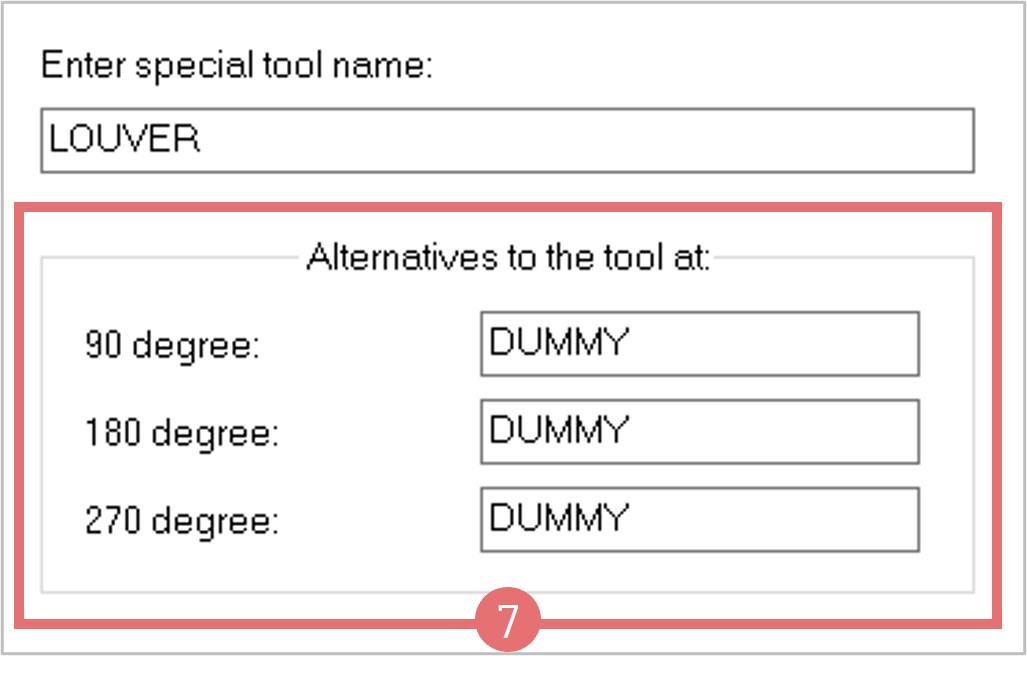
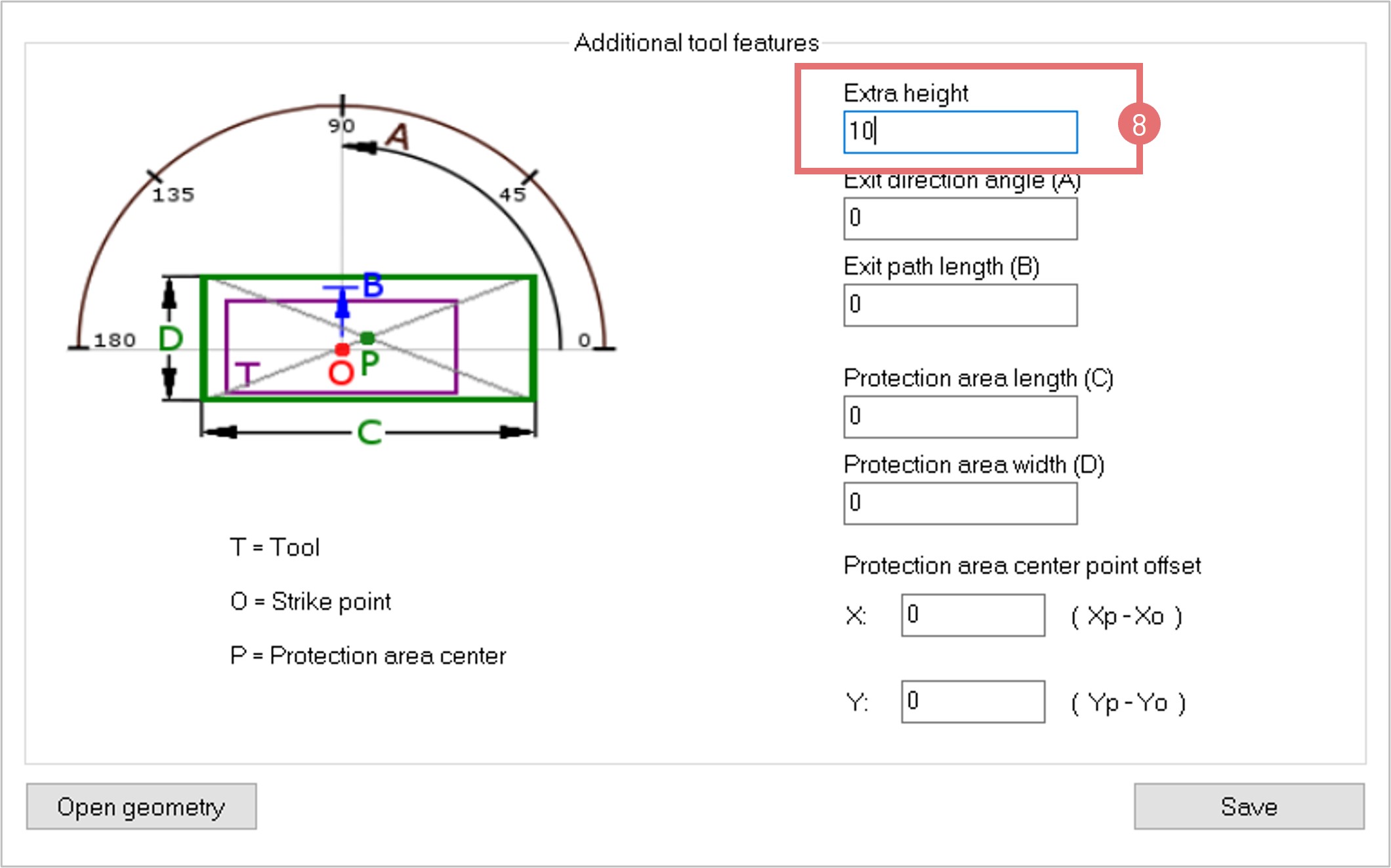
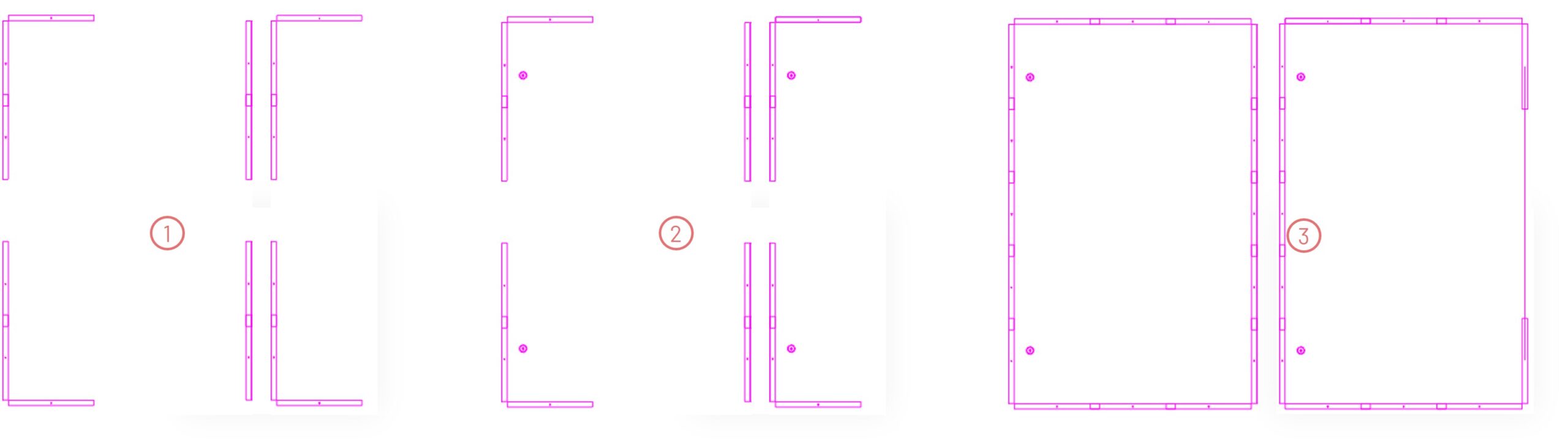
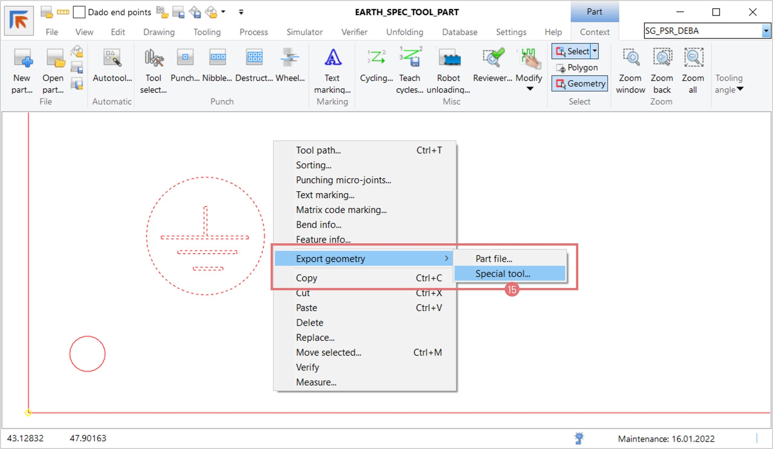
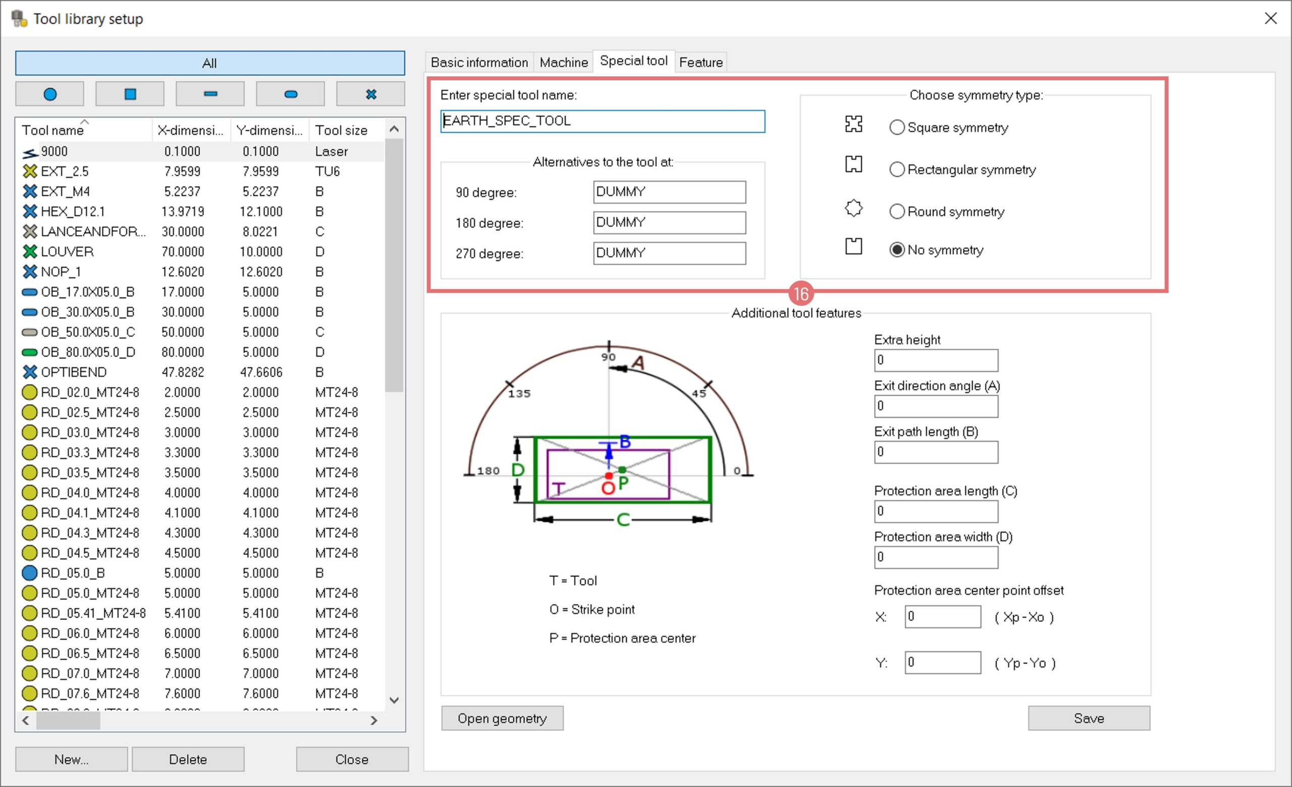
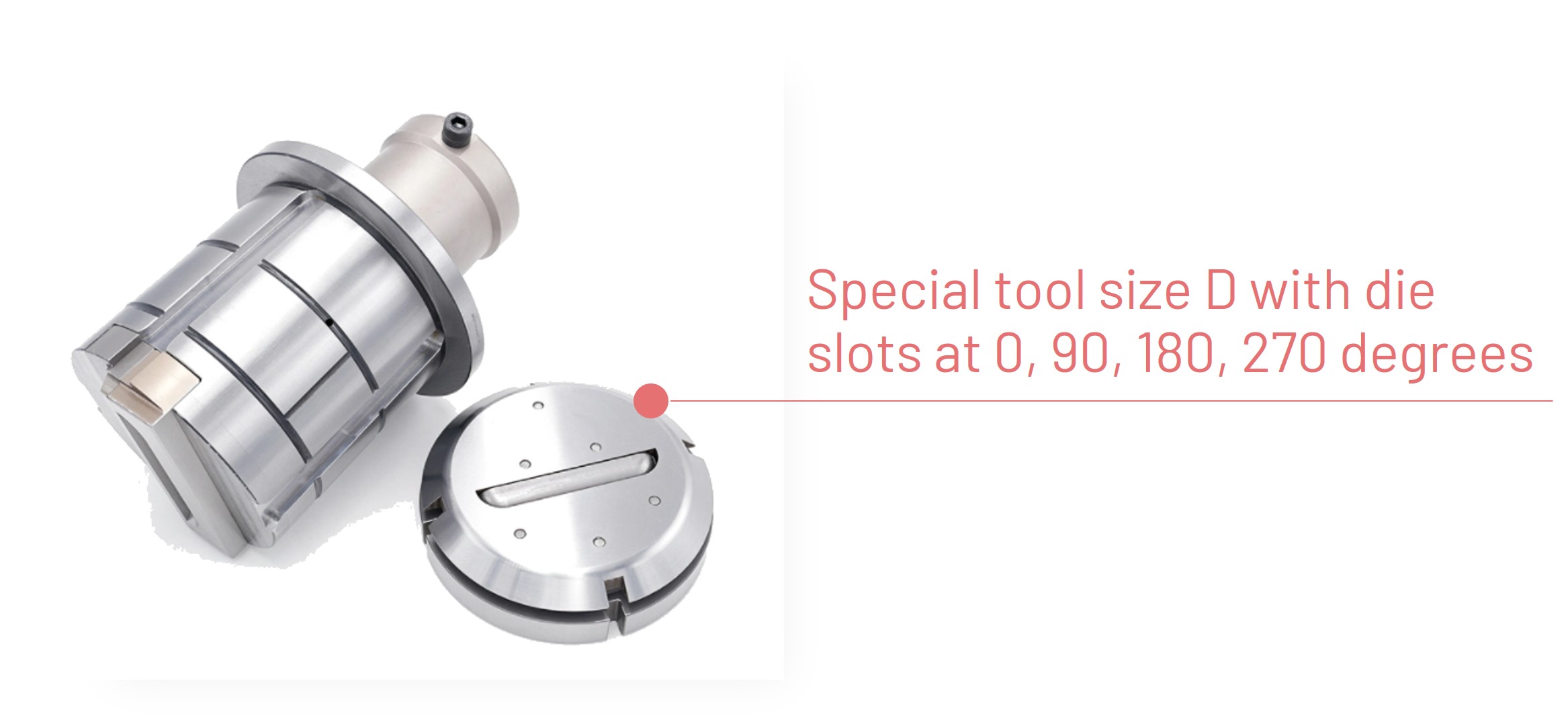
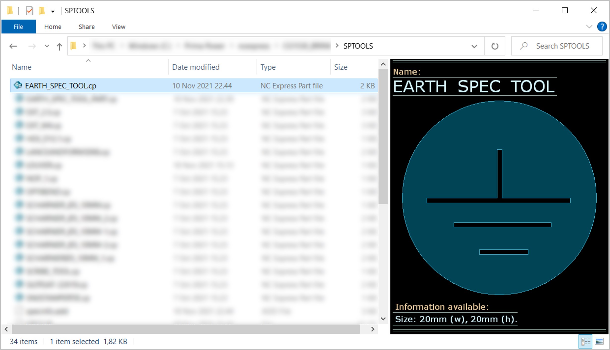
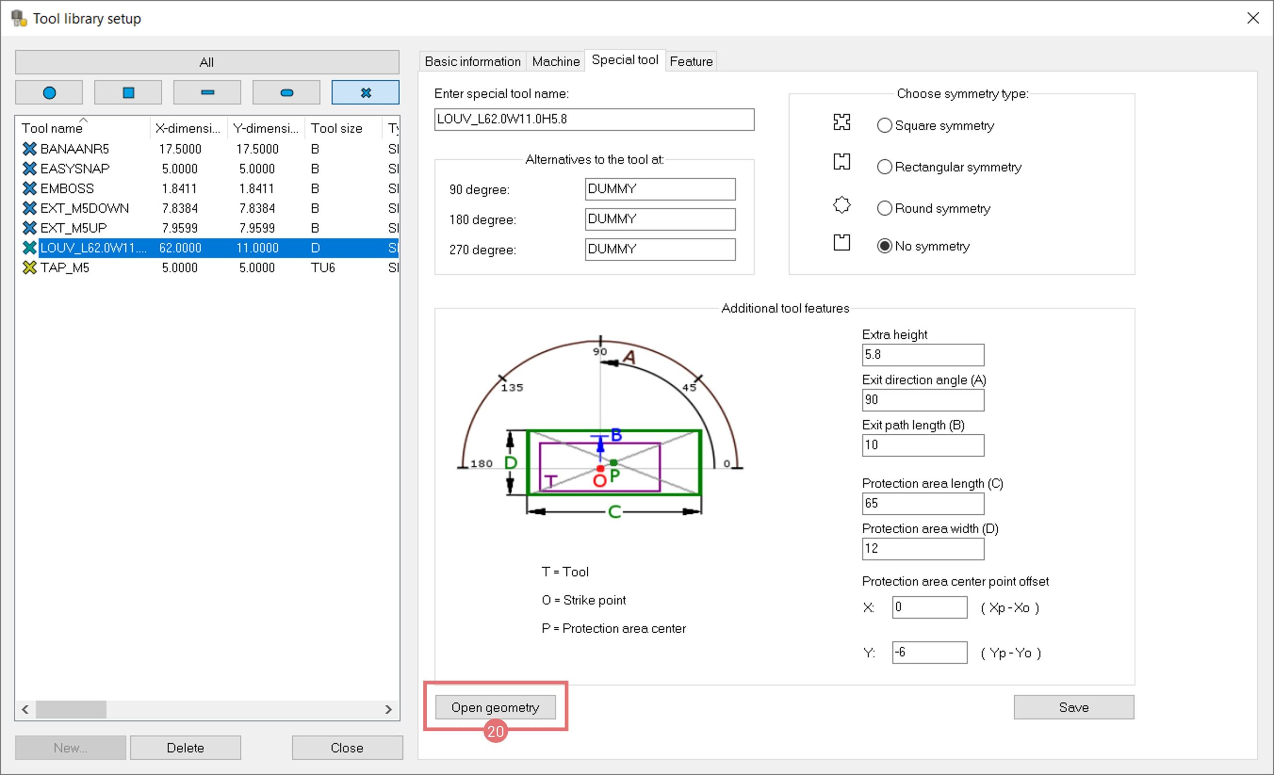
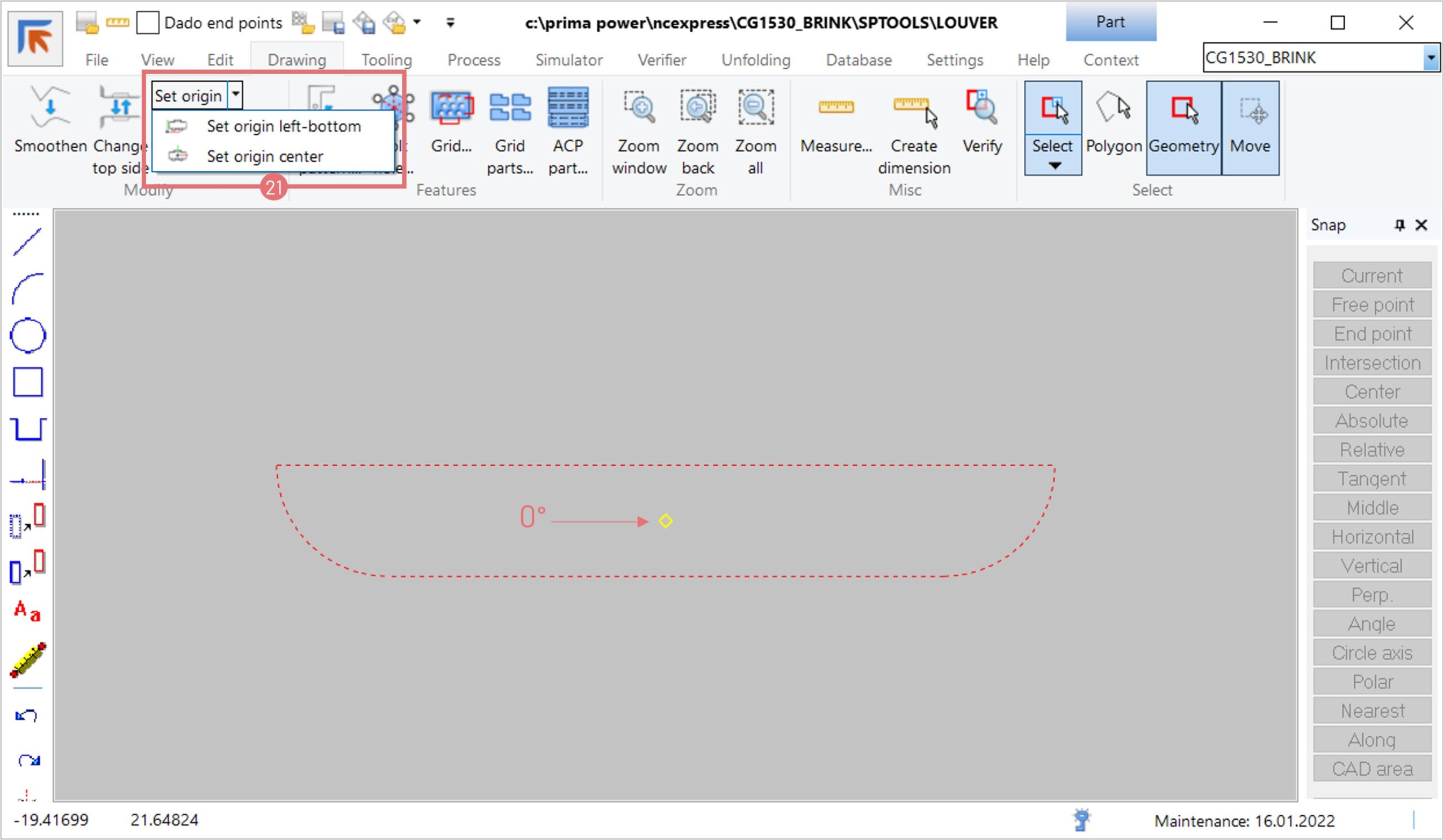
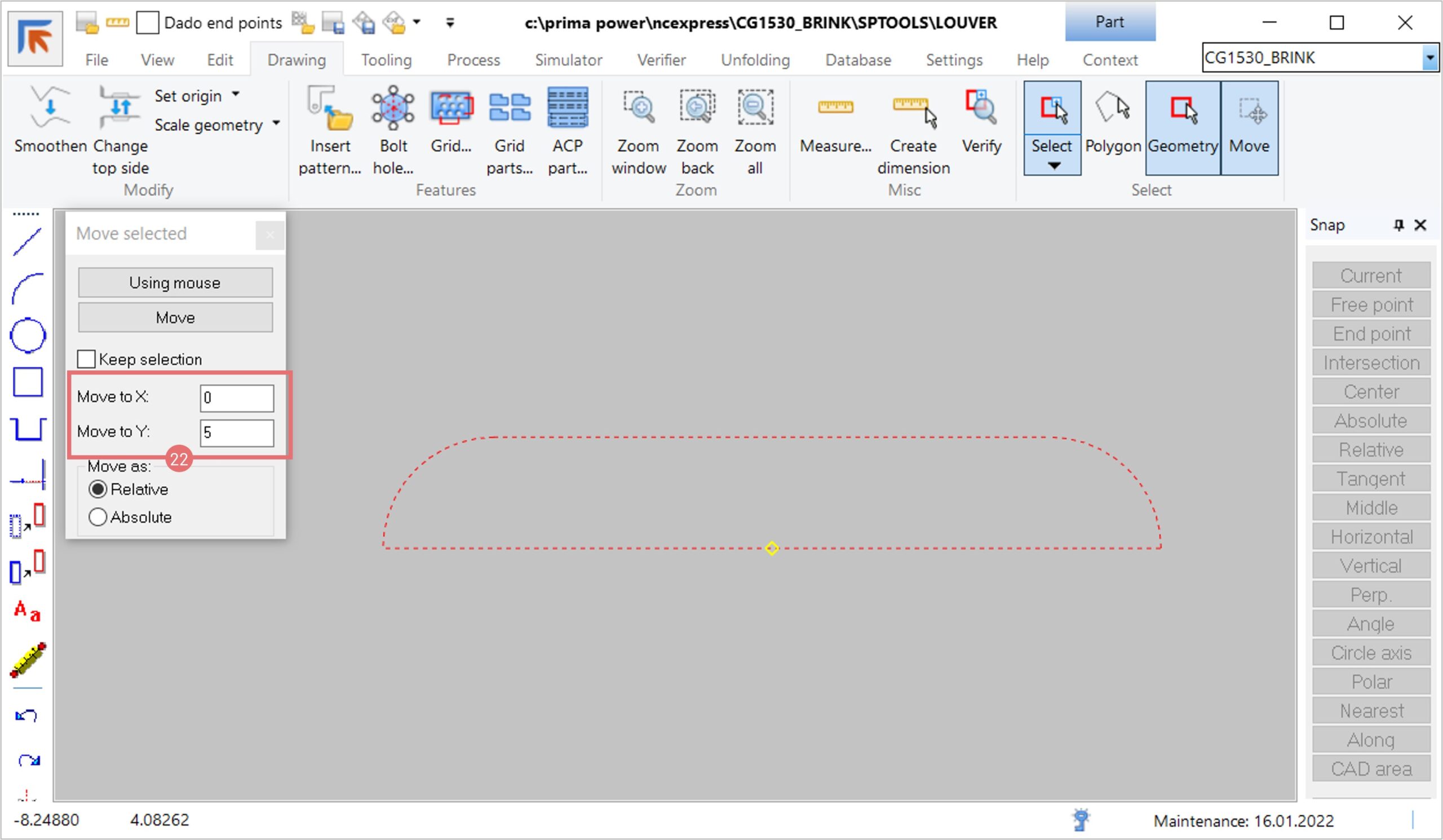
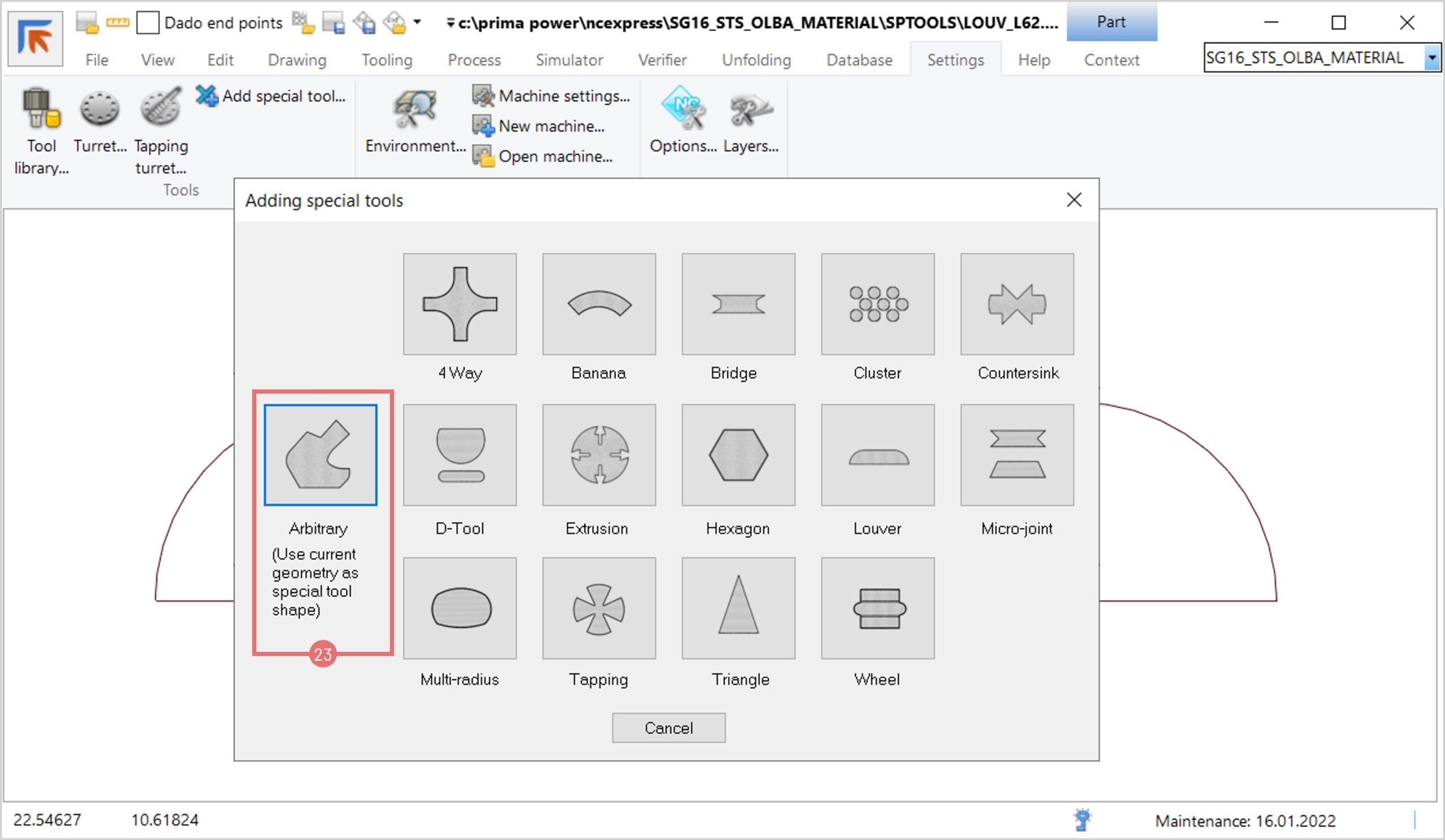
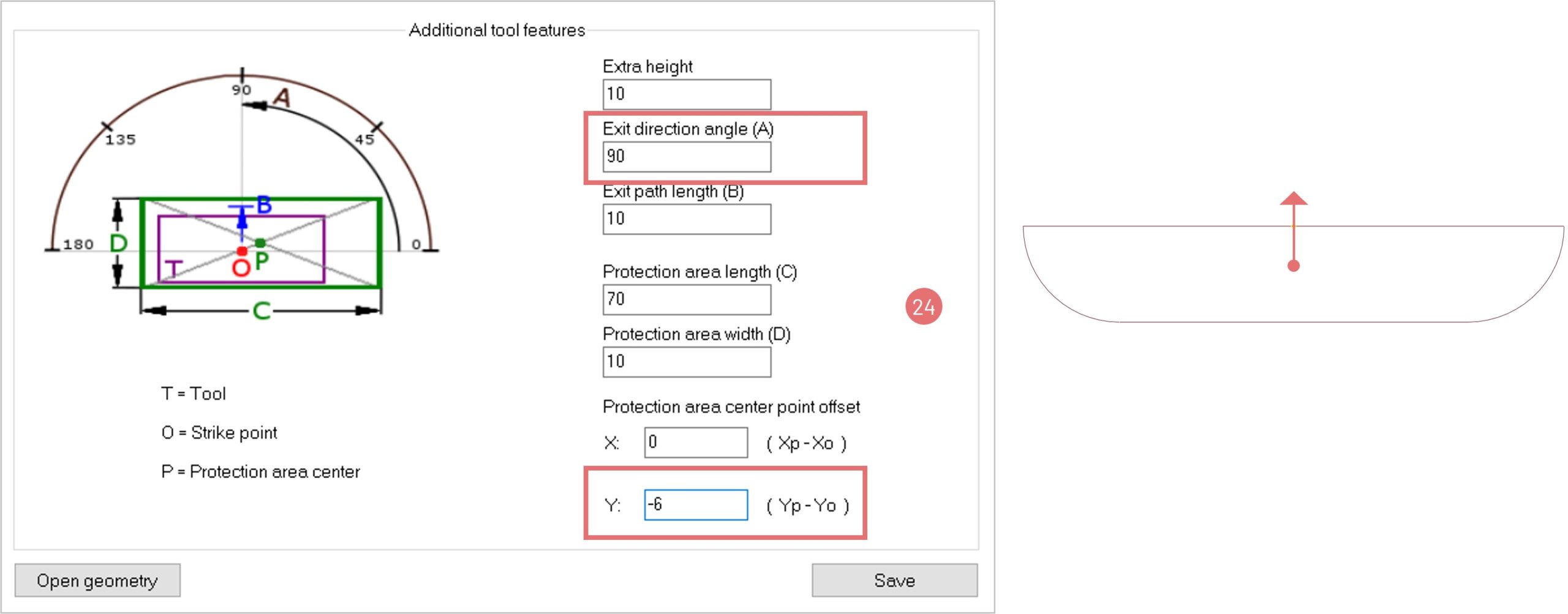
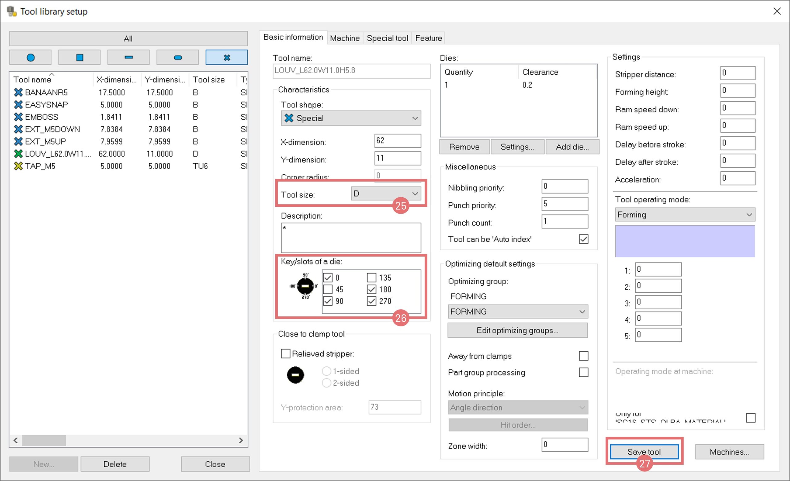
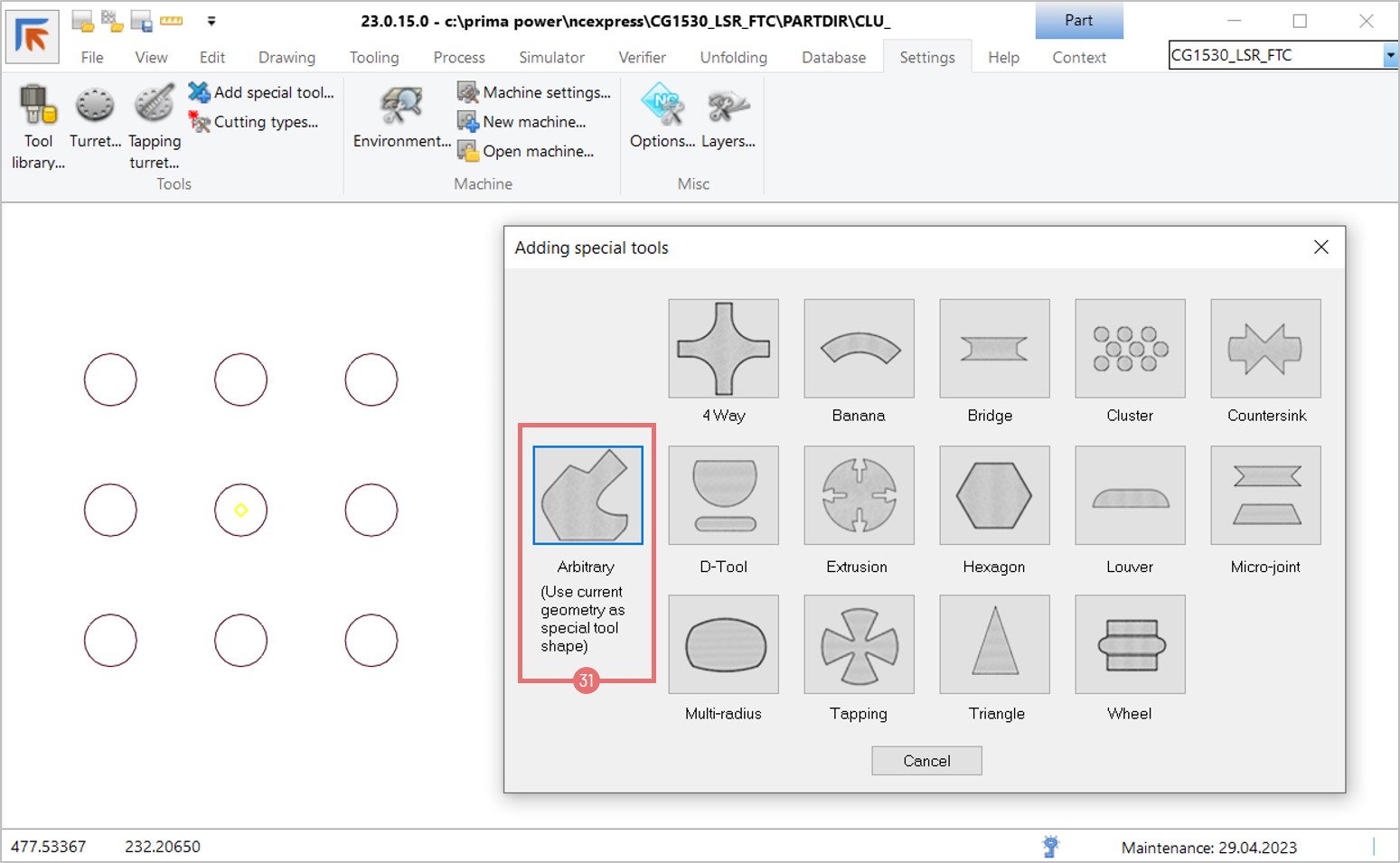
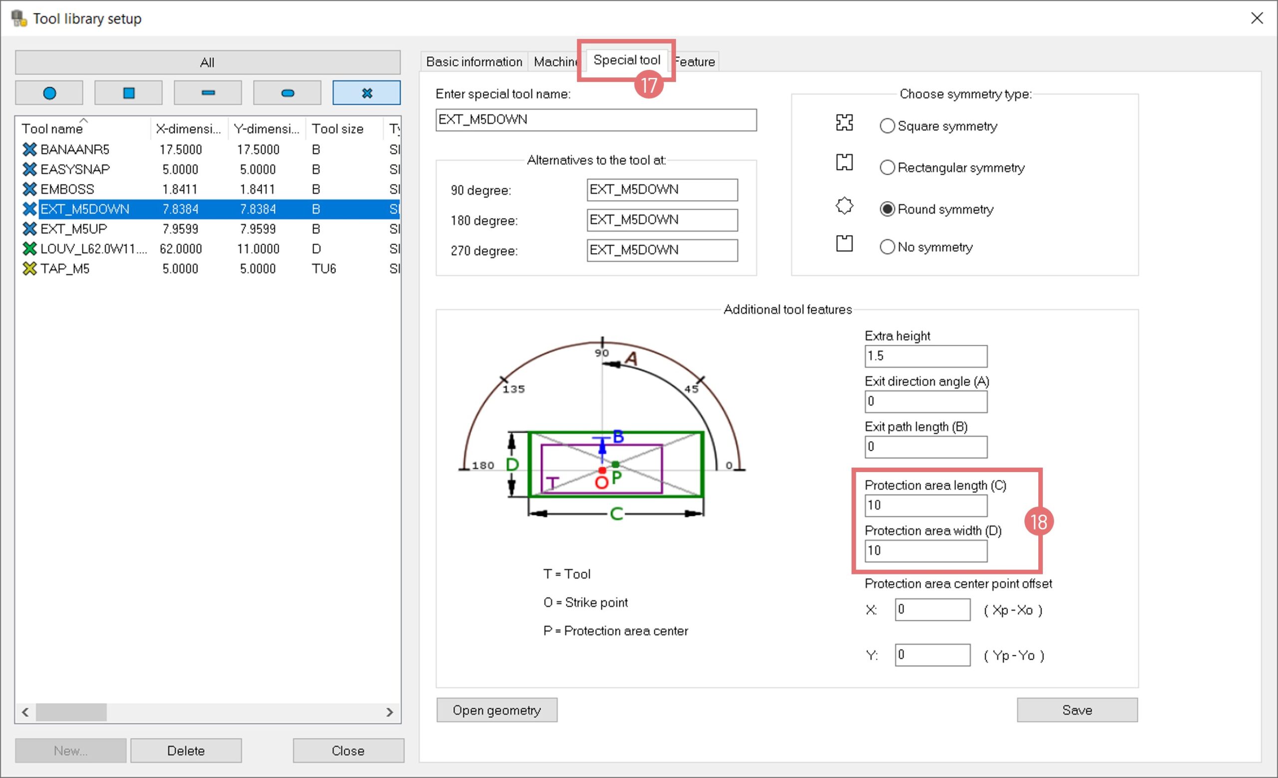
- Usability Enhancements: Creating standard tools from part geometry, triangular-shaped dimple feature recognition, nibbling priority settings, and marking selected parts as completed in the order database.
- Windows Support: Compatibility with Windows 7, Server 2012 to 2022, and the latest Windows 10 and 11 versions.
Important Notes on 32-bit vs. 64-bit Builds:
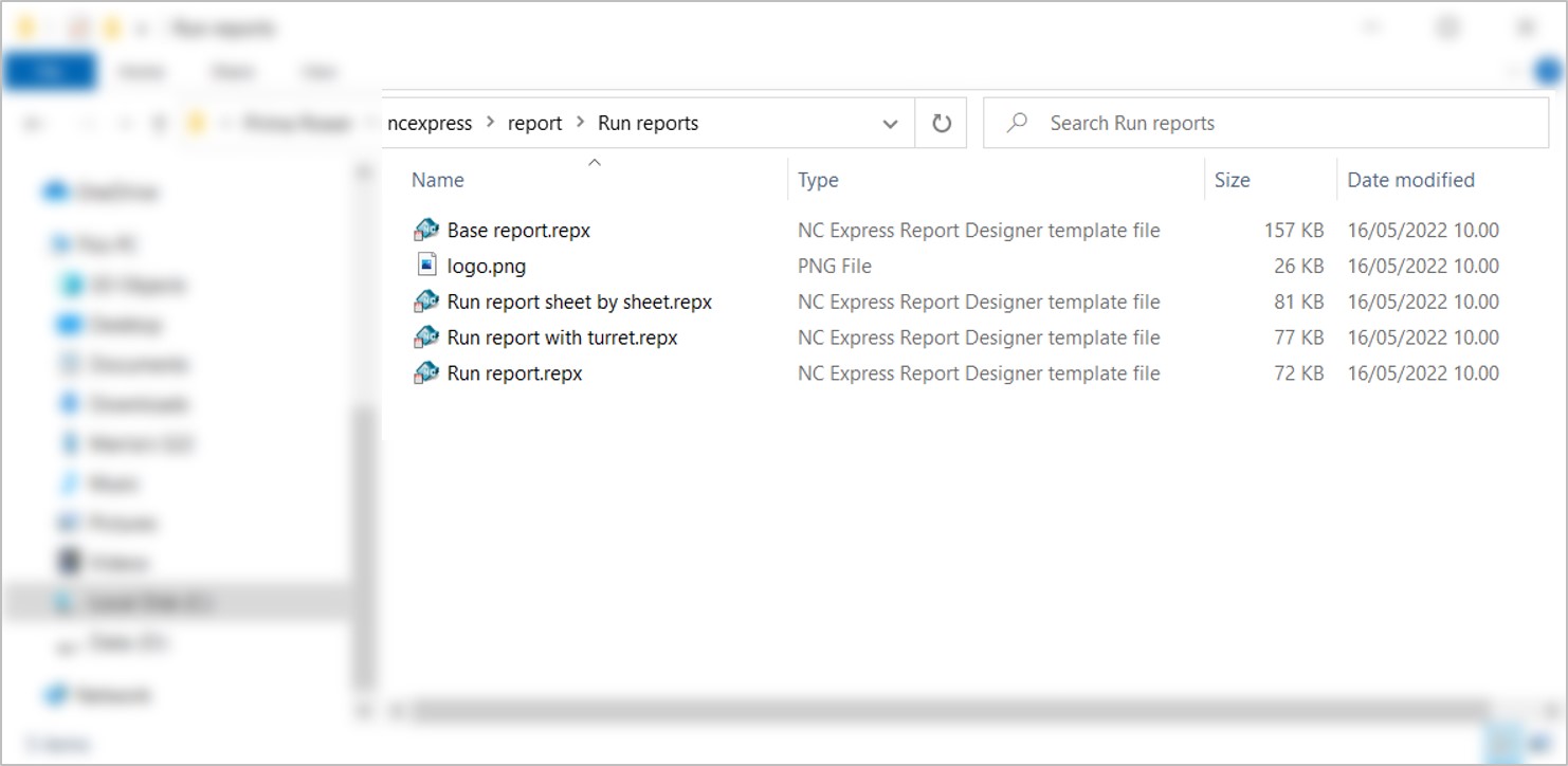
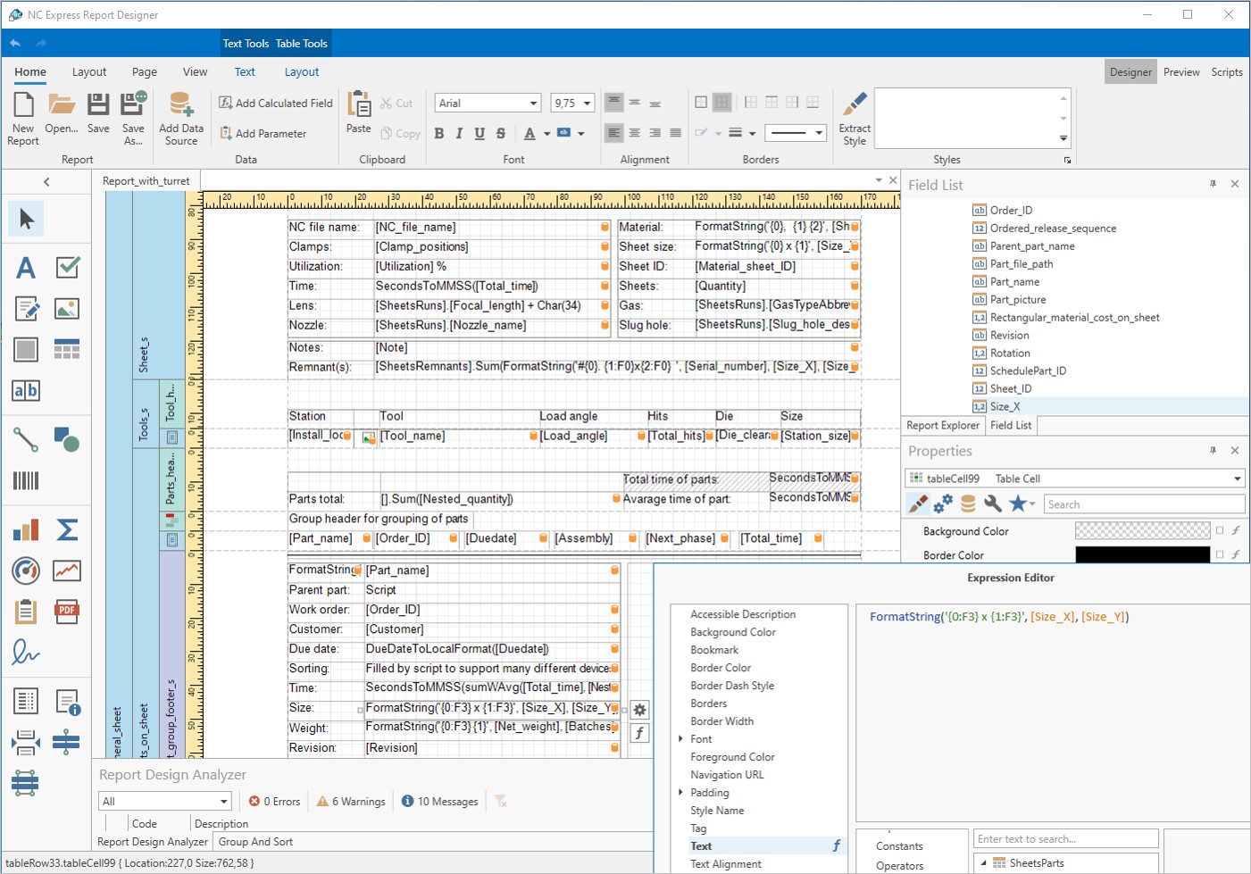
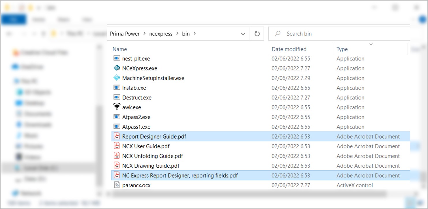
- 64-bit Build: Recommended for new customers. Note that old customized 32-bit report templates cannot be used and must be recreated.
- 32-bit Build: Backwards compatible with older versions. Recommended for updates if you currently use the 32-bit version.
- Integration Considerations: If you have software integrated with NC Express using the ParaNCX-interface, please contact Prima Power before updating to the 64-bit build. This affects applications such as Tulus Office Premium, Tulus Office Power Processing, Batch Processing, and PowerPlan, which also need to be compiled in 64-bit.